
Small outboard motors can often be a low priority when it comes to maintenance. David Parker found out the hard way that his trusty little engine had been ignored for too long
Rebuilding an outboard motor gearbox: step-by-step
As I turned around and headed back to the pontoon, the look on a fellow boat owner’s face said it all, writes David Parker.
He clearly felt my pain – but neither of us felt as bad as my outboard engine.
It sounded as though someone had put a bag of nuts and bolts inside a blender. Surely not? Not my reliable little Suzuki 2.5?
It had served me faithfully for 10 years: always starting easily, never missing a beat, light to transport, would push four of us in a loaded tender without a whimper.
Would do anything you asked of it, really.
It hardly seemed to use any fuel either, and never forced me into a chandlers: a well-appreciated cheap date compared to everything else in the fleet.
Should I stop the eulogy yet… who mourns an engine like this? I do – there’s more.
At times, on a frosty morning at first light, can anyone know how sweet that engine sounded starting up at dawn to take me home down the river?
On water-sampling exercises for my daughter’s degree dissertation, I worked out that the engine took us an equivalent distance of Cherbourg and halfway back.
But now it was in a bad way – and those with a fondness for machines and tools will understand it when I say I felt genuine guilt at having to let this old friend down.
You see, I’m ashamed to say that I can’t remember the last time I had serviced it properly.
Every time I used it I religiously flushed it out with fresh water and then stored it under cover, but that was it.
While so many other things had had money spent on them – and sometimes serious money – when was the last time I even looked at this engine? I always took it for granted that it would go and it always did.
However, things had come to a head the day before. I had set offriver, and about halfway the engine started to sound wrong and lose power.
That evening, when I checked it in the car park, I saw that the shear pin had broken and realised I must have hit something in the water without knowing it.
I accordingly replaced the shear pin, but that couldn’t have been the real problem.
The next day things sounded even worse, and that was when the noises of tortured metal started. Even then it got us back downriver, but it was clearly in poor shape.
Judging by where the noise was coming from, I knew it was the outboard motor gearbox, so when I got back I drained it.
The engine oil looked like decomposing black molasses and, even worse, there was water in it.
Somehow a gearbox seal must have been damaged at the same time as the shear pin was broken.
With decent oil, it would probably have survived, but not with this stuff.
On further inspection, it was clear that the outboard motor gearbox was a write-off.
Some might feel that this small, ageing engine’s days were now over and that donating spares would be the best it could hope for. No, you’re right – how could I?
I had been so impressed with the engine that I even bought a newer Suzuki 2.5 to tide me over while it was being fixed – and this is how I carried out the work.
Rebuilding an outboard motor gearbox:: the strip-down
Credit: David Parker
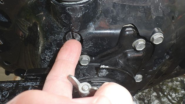
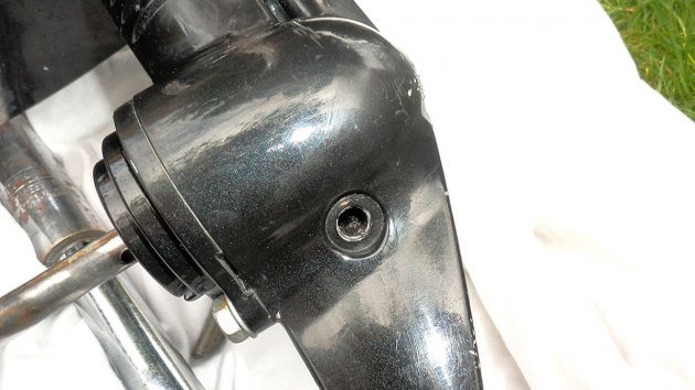
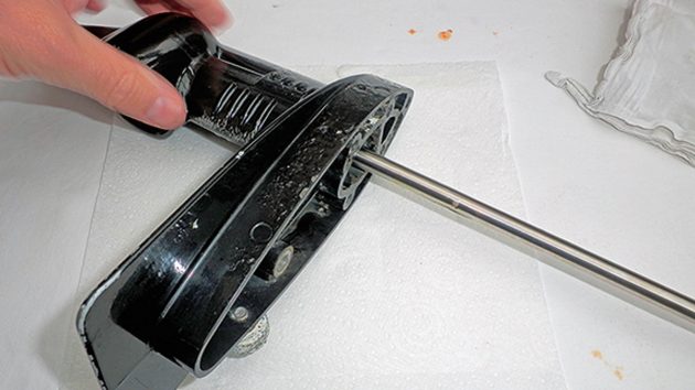
1. The first job was to drain the engine oil; to do this, the engine needed to be upright. Unscrew the engine oil drain plug, which, in this case, is sited under the tiller on the main engine block.
Credit: David Parker
2. Ideally, any engine oil should always be drained when the engine is warm unless damage is suspected, as in this case. Note that the old oil is heavy and black and clearly needs replacement.
Credit: David Parker
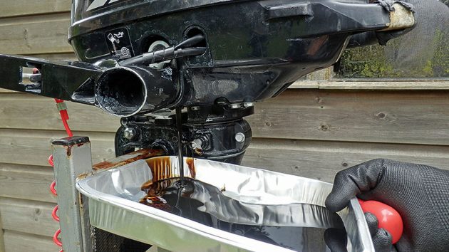
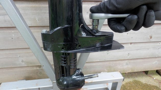
3. Next, locate the gear oil drain plug which is on the lower leg at the base of the gearbox. In routine maintenance, it is not necessary to remove the propeller, but it was taken off in this case due to the gearbox rebuild.
Credit: David Parker
4 When the gearbox oil was drained it could be seen that it contained both water and deposits of what looked like debris from damage caused to components in the gearbox.
Credit: David Parker
5. On further investigation it could also be seen that there were fine deposits of swarf caught in the threads of the drain plug hole. Swarf is caused by metal surfaces cutting or abrading each other – a worrying sign.
Credit: David Parker
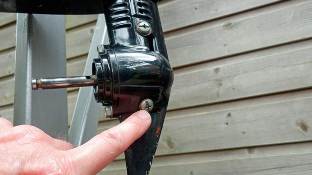
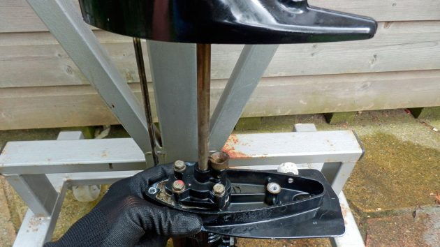
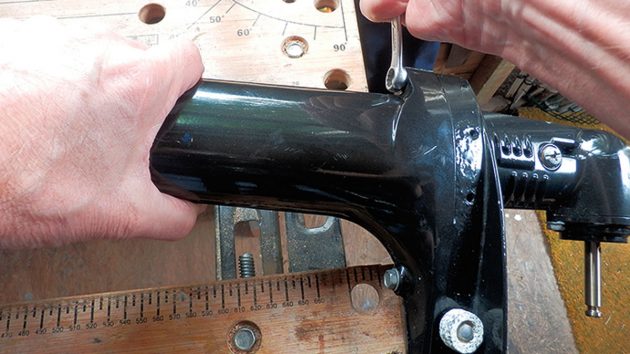
6 When the oil was drained, the lower unit containing the gearbox and water pump was removed by unscrewing two retaining bolts.
Credit: David Parker
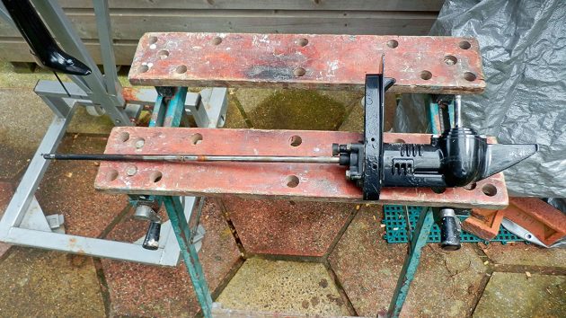
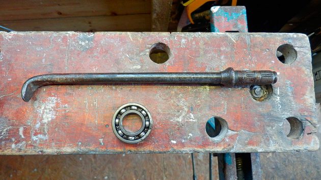
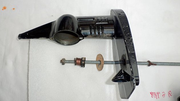
7. With the bolts removed, the gearbox unit could now be removed. The long thin bar on the left is the gearshift rod, and the thicker rod in the centre is the driveshaft which passes through the water pump housing. Right of this is a grommet which houses a tube fed by the water pump.
Credit: David Parker
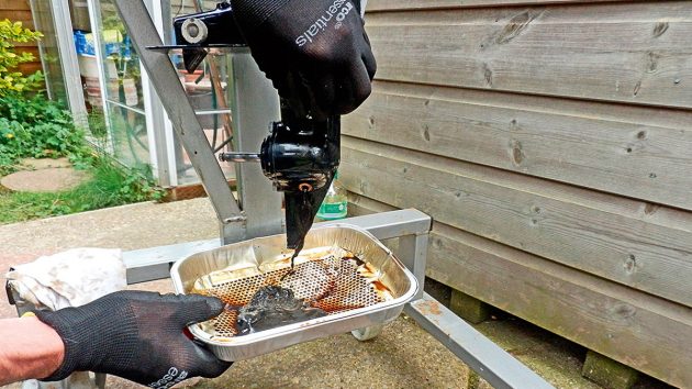
8 From this orientation we can see the water pump tube indicated by the tip of the screwdriver. The gearshift rod is on the right.
Credit: David Parker
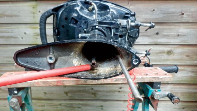
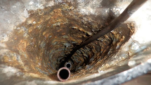
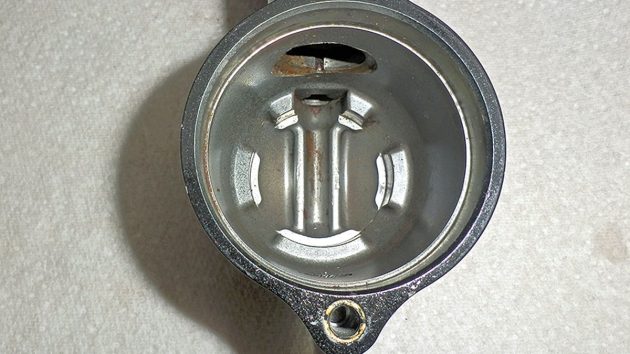
9. Despite regular flushing with fresh water, deposits have still formed inside the driveshaft housing over time. If parts are accessible, these could easily be scraped away.
Credit: David Parker
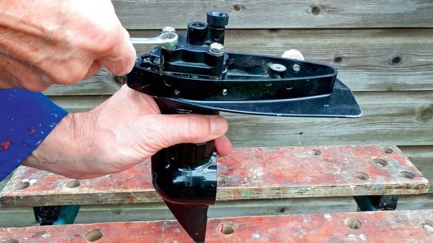
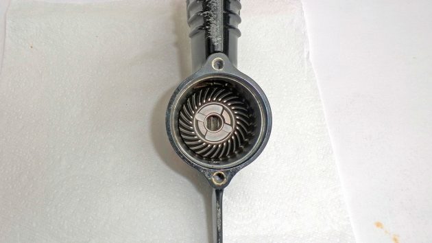
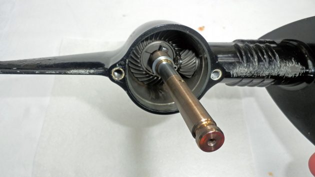
10. Here we see the lower leg and gearbox removed with the driveshaft and propshaft still in position. This is the part of the outboard motor you would need to work on if you were just changing an impeller.
Credit: David Parker
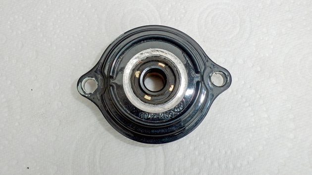
11. The propshaft cover was unbolted from the front of the gearbox case.
Credit: David Parker
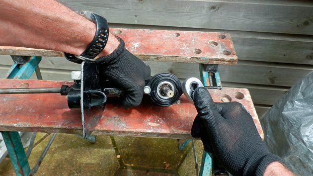
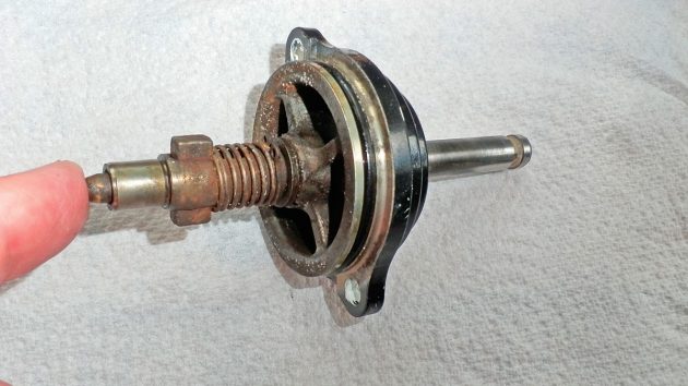
12. When the propshaft cover was removed, the propshaft and clutch assembly could be withdrawn. The oil shows further signs that it has been partly emulsified due to water getting through the seals.
Credit: David Parker
13. At the end of the propshaft is a pushrod pin leading from the clutch mechanism. This is operated by the gearshift rod going up and down to engage and disengage gear.
Credit: David Parker
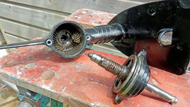
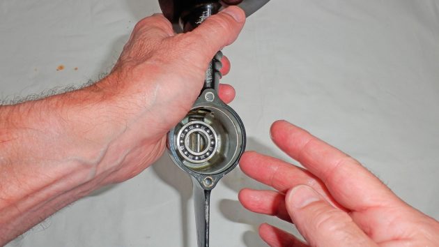
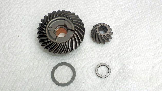
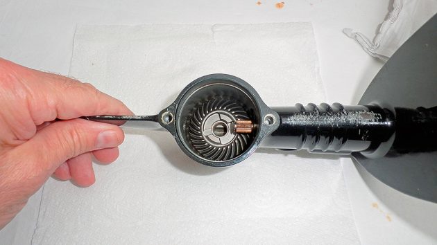
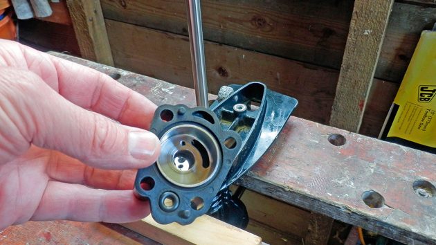
14. The larger cog at the rear is the forward gear to engage drive and is driven by the smaller pinion gear on the right. On the small cog, we can see the splined end of the driveshaft, and normally this should be retained in position by a circlip. In this case, it was missing and must have disintegrated, which explains the swarf in the gearbox oil.
Credit: David Parker
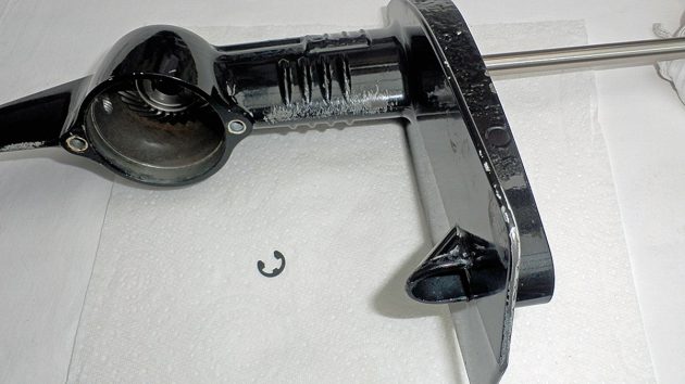
15. With the retaining circlip missing, the driveshaft simply pulled out of the lower leg. Four bolts were then undone to remove the water pump housing.
Credit: David Parker
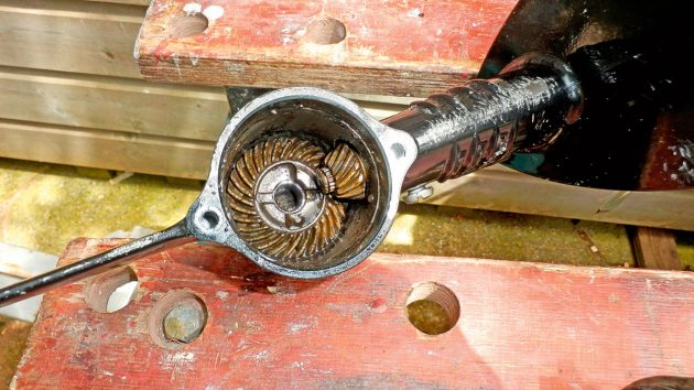
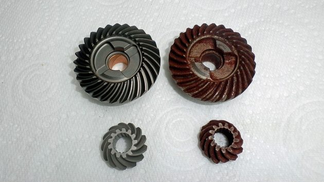
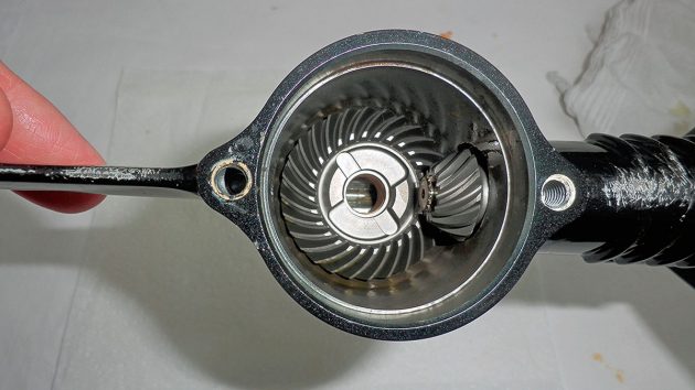
16. With the driveshaft removed, the gears just lifted out. However, while I awaited new parts they quickly rusted because of the salt water in the gearbox. It can also be seen that the teeth are badly worn compared to the new gears.
Credit: David Parker
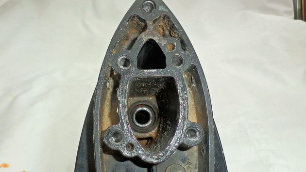
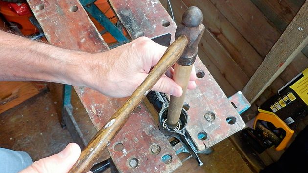
17. In the back of the gearbox case, the bearing had also rusted and seized in position. To remove it, I used a homemade tool – an old screwdriver with the end heated and bent to form a small lever. With this, I was able to prise out the bearing after soaking it in penetrating oil.
Credit: David Parker
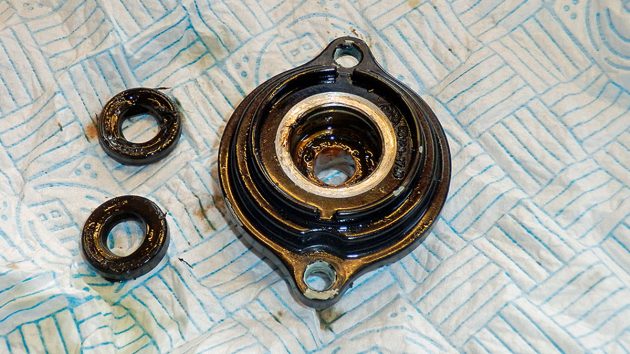
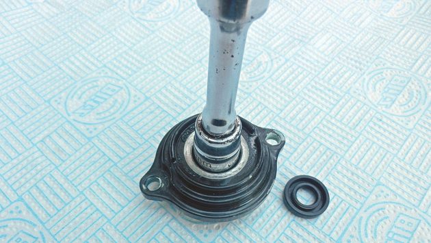
18. With the propshaft removed it could be seen that the seal for the end of the propshaft housing is worn, and I could also detect small splits in the rubber.
Credit: David Parker
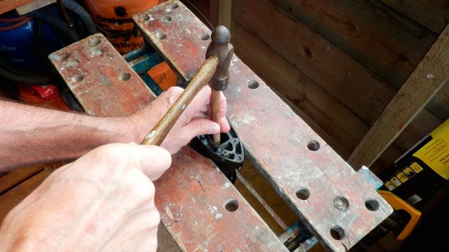
19. There were in fact two seals back-to-back in the propshaft housing, and these were tapped out with a nail punch.
Credit: David Parker
20. The next seal I needed to remove was the one for the driveshaft, seen here. This was trickier because both the seal and bush for the driveshaft are firmly housed in a recess in the gear case under the water pump.
Credit: David Parker
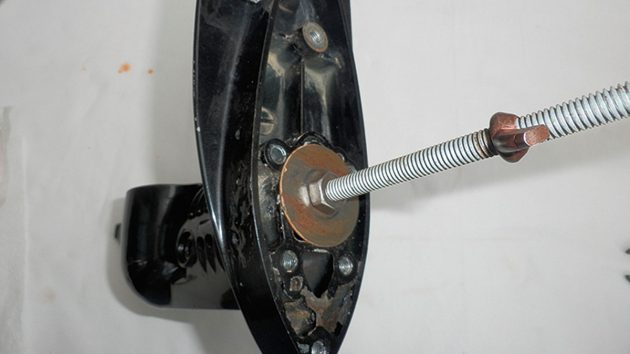
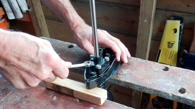
21. To remove these I used a home-made puller which comprised a length of studding passing through the driveshaft housing with a large washer at the top and nuts at either end. The wing nut was just to hold it in place while I lined things up.
Credit: David Parker
22. Underneath my puller was a nut with a smaller washer. By tightening the top nut I drew out the bush and seal as shown.
Credit: David Parker
23. The final job was to thoroughly clean the gear case housing before reassembling it with the new components.
Rebuilding an outboard motor gearbox: putting it all back together
Credit: David Parker
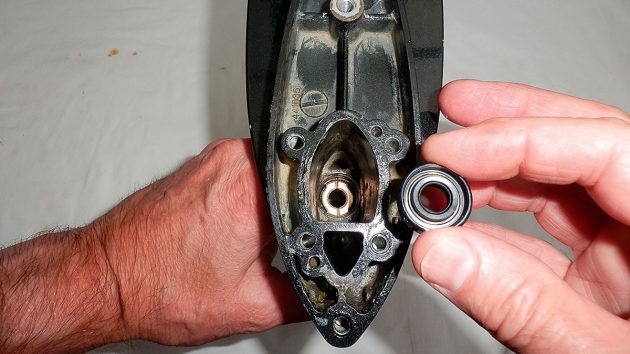
1. The first thing to go in was the new bearing, which fits at the back of the gear case and the forward gear butts against it. To prevent damage it was greased at the sides and then tapped home by a wooden dowel the same diameter as the bearing.
Credit: David Parker
2. The bearing is a tight fit, and it is essential that the bearing is correctly positioned in the bearing housing to ensure everything else fits.
Credit: David Parker
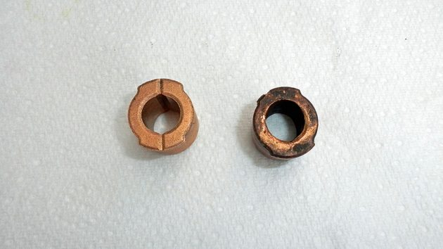
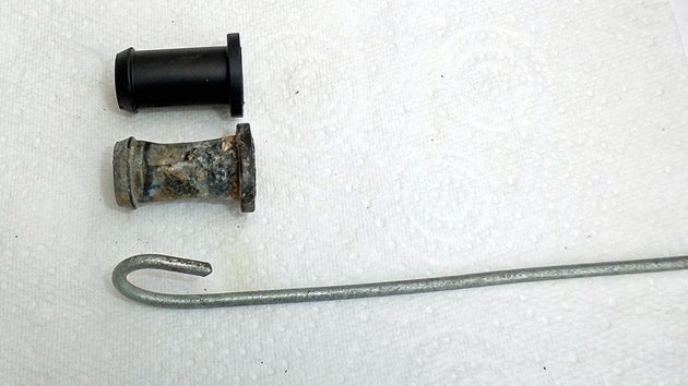
3. On the left is the new driveshaft bush and on the right is the old one which it replaces.
Credit: David Parker
4. Again, a piece of wooden dowel with the correct diameter proved the ideal way to tap home the bush.
Credit: David Parker
5. The new bush sits tightly inside the gear case to house the driveshaft. Then a new seal is tapped down on top of it.
Credit: David Parker
6. The forward gear(larger) and the pinion both sit on shims.
Credit: David Parker
7. The forward gear in position on a shim and against the bearing.
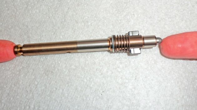
Credit: David Parker
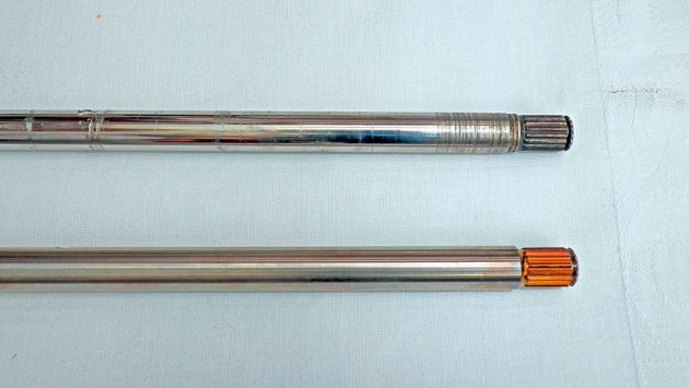
8. Scoring can be seen at the end of the old driveshaft which was caused by the gearbox damage. The shaft has splines at both ends to engage the pinion at the bottom and crankshaft at the top.
Credit: David Parker
9. The new driveshaft is carefully fed down into the gear case through the seal and the bush.
Credit: David Parker
10. The driveshaft is fed down until the splined end emerges. Note the recess at the end of the shaft for the circlip.
Credit: David Parker
11 The pinion gear is fed over the splined end so that it engages with the forward gear.
Credit: David Parker
12. A circlip is fitted to retain the pinion gear in position.
Credit: David Parker
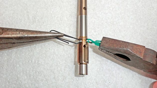
13. I didn’t have circlip pliers, but I found that two paper clips could be used to fit this circlip in position over a lip in the propeller shaft. (The hole two-thirds along the shaft is for the shear pin).
Credit: David Parker
14. The assembled new propshaft and clutch. The return spring engages the clutch dog to the right with the gear when the pin (indicated by the finger) is released by the gear rod.
Credit: David Parker
15. The propshaft in position with the shifter clutch dog against the shoulders machined into the face of the forward gear.
Credit: David Parker
16. New seals are fitted into the propshaft housing. A socket the same diameter proves the ideal way to tap them home.
Credit: David Parker
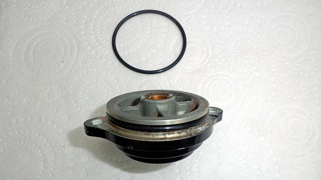
17. A new O-ring is then greased and fitted to the inside face of the propshaft housing.
Credit: David Parker
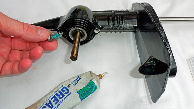
18. Retaining bolts are lubricated with waterproof grease before refitting the propshaft housing to the gear case.
Credit: David Parker
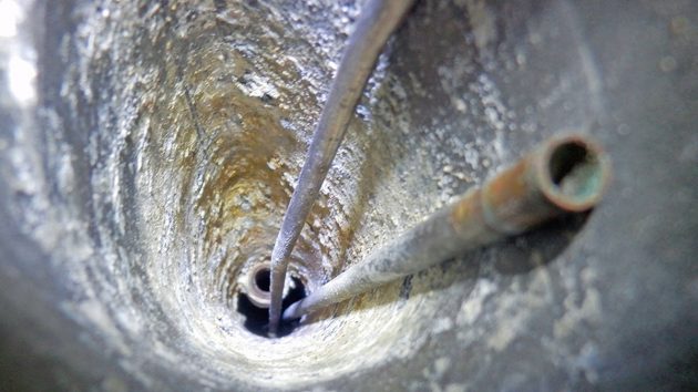
19. Next came the fiddly job of removing the old driveshaft rubber guide right up inside the leg and fitting a new one.
Credit: David Parker
20. Again, a homemade tool did the job, and a long wire hook was made to remove the old guide (below) and fit the new one – after several attempts.
Credit: David Parker
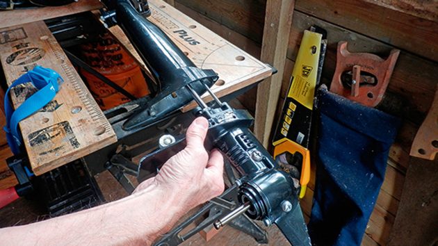
21. The lower unit with the gearbox assembly was then slid back into the leg, ensuring the driveshaft engaged with the crankshaft and that the gear rod and water pump tube lined up in their respective positions.
Credit: David Parker
22. The bolts for refitting the lower unit were also lubricated with waterproof grease.
Credit: David Parker
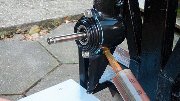
23. Gearbox oil was fed in with a syringe through the drain plug until it emerged out of the gear oil level plug at the top. Both plugs had new washers fitted.
Credit: David Parker
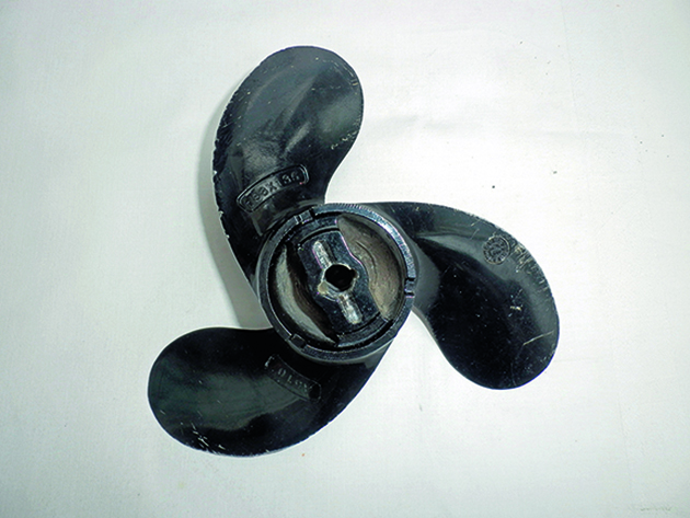
24. The prop went on next, but note the slot in the back which must match up with the shear pin which fits through a hole in the shaft.
25. New engine oil was then added along with a new washer for the drain plug.
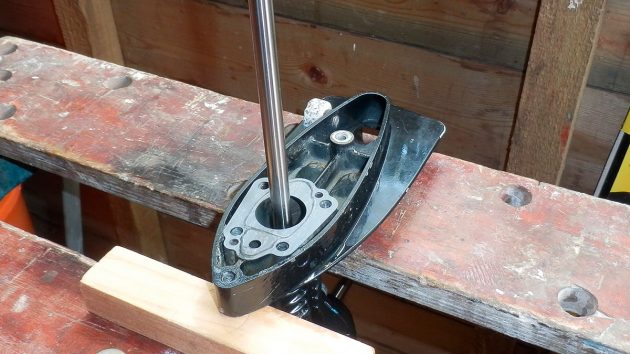
Refitting the water pump
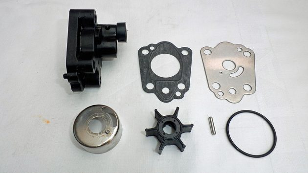
The components of the water pump before assembly. Credit: David Parker
1. First, the lower gasket goes on top of the case housing.
Credit: David Parker
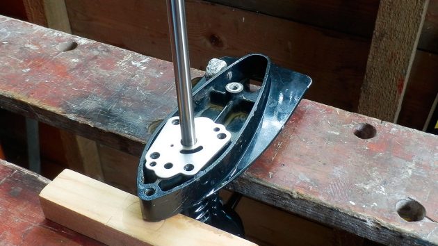
2. The metal water pump gasket then sits on top of the soft gasket.
Credit: David Parker
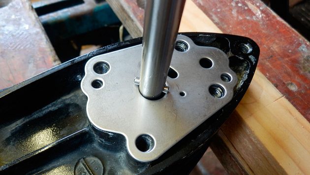
3. The impeller pin is carefully placed through the driveshaft.
Credit: David Parker
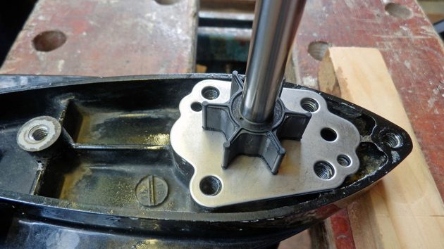
4. A slot in the base of the impeller fits over the top of the impeller pin.
Credit: David Parker
5. The impeller case goes inside the housing and then a new O-ring is fitted.
Credit: David Parker
6. The water pump case is slid down over the driveshaft and tightened down with four greased bolts.
Credit: David Parker
Continues below…

How to service a marine diesel engine in 12 simple steps
It was time to service the marine diesel engine on our Maxi 84 cruiser. Knowing how to diagnose and fix…

Buying a new or used outboard motor? Professionals share their tips to make sure you avoid the pitfalls
From horsepower to shaft length and tilt-angle to 2- or 4-stroke, Ali Wood highlights the different features you should consider…
Why is my outboard so unreliable?
Colin Staple's unreliable outboard is spoiling his sailing. Stu Davies suggests how to improve its performance

How to troubleshoot an outboard engine – video guide
This is our guide to basic outboard troubleshooting for a small petrol four-stroke outboard engine. If you’ve got a problem…
For more boating news, features and expert advice, take out a PBO subscription

A subscription to Practical Boat Owner magazine costs around 40% less than the cover price.
Print and digital editions are available through Magazines Direct – where you can also find the latest deals.
PBO is packed with information to help you get the most from boat ownership – whether sail or power.
-
-
-
- Take your DIY skills to the next level with trusted advice on boat maintenance and repairs
- Impartial in-depth gear reviews
- Practical cruising tips for making the most of your time afloat
-
-
Follow us on Facebook, Instagram, TikTok and Twitter