
Richard Thomson explains how he gave his 1983 Trident Marine Voyager 38’s electrical system a complete and cost effective overhaul
Buying the 1983 Trident Marine Voyager 38 Namika in Greece, post-Brexit and post-Covid lockdowns, felt a little like adopting a stray.
Locked up on her stand and slightly neglected, we knew she needed work, but the heart saw past that and trusted all would be worth it.
Three years of ownership, two extended seasons living aboard, several thousand miles and (whisper it) nearly seven months living in a boatyard later,
I would mostly say the heart was right.
Designed in the 1980s by Angus Primrose, of Gipsy Moth IV fame and the mentor of Bill Dixon, the 38ft Voyagers were built in Portchester by Trident Marine.
Namika is a comfortable deck saloon with a long-chord encapsulated keel directly under the engine and tankage.
While a little sluggish in light airs, she shows real pedigree as the breeze freshens; Namika is superbly balanced at the helm and goes like a train at Force 4 and beyond.
We regularly average six knots on all points of sail for hours at a time and have sustained well over seven knots on numerous occasions, again on all points of sail.
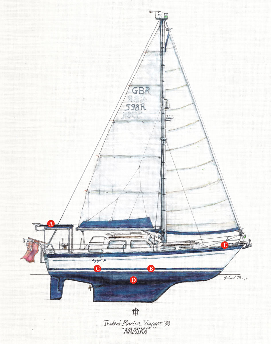
Location of the main components- keeping the chargers, batteries and inverter located close together allows the wiring runs to be extremely short. It also means the weight is in the centre of the boat
Additionally, that long-chord keel and raked bow make her extremely comfortable in a seaway.
However, we didn’t anticipate how much work she required; perhaps a familiar realisation for many other first-time boat owners!
We’ve since re-rigged (planned), replaced two water tanks (unplanned), replaced the engine (not entirely unforeseen, but hope dies last), and replaced the batteries and DC system.
‘Small’ jobs included replacing the old Flavel Vanessa cooker, adding davits, a second fridge, an autopilot, and replacing various pumps, plumbing and seacocks.
There was enough scraping, sanding, painting and varnishing that at times, we felt we’d bought the Sistine Chapel.
Except for the engine installation we have done everything ourselves, learning as we go.
Steep learning curve about boat electrics
The boat electrics project stands out because there were several interconnected parts to it.
It’s also a job many boat owners might be considering, given the improvements in generation and storage technology, and with life seemingly ever more electric.
Unfortunately, beyond some distant high school physics I was a complete novice when we realised something had to be done, and frankly, I was quite scared of electricity.
Sure, I knew there was a difference between positive and negative. I sort of knew what watts, volts and amps were.
However, what explains my initial caution is that my prior practical electrical experience amounted to changing a handful of lightbulbs and getting a shock from an electric fence as a child!
But, I did a lot of research about boat electrics, and I have condensed what I learnt in this article in the hope I might help someone similarly as (un)informed as I was.
If you know the difference between positive, negative, watts, volts and amps or perhaps even a little more, you’re no worse prepared than I was.
For those pondering a similar boat electrics project, maybe this article will encourage you to do it and perhaps indicate some points or terms to research to find a solution which is appropriate to your boat and cruising needs.
A brief disclaimer: electricity has the potential to be dangerous, and this is only intended as an overview of the thought process and steps I went through. You should do your own research to determine what is right for you and your boat. If in doubt, ask a professional.

The cables from the old solar charger didn’t have lugs– they were just jammed between washers
Making do
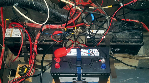
When we bought her, Namika had two 12V 100Ah sealed lead-acid domestic batteries and one 100Ah sealed lead-acid starter battery.
All were flat, with the domestic loads wired straight off their batteries in a bird’s nest tangle of copper known euphemistically as ‘star wiring.’
The reality was the wires were unlabelled, much was defunct, everything was intertwined, and not all of it was fused.
However, after charging via shore power, the batteries seemed to hold a charge.
Knowing that if we started to pull one wire the whole thing would unravel, we decided to replace the starter battery for our shakedown cruise in 2022 but stick it out with the domestics and their bird’s nest of wires.; three aged solar panels ran one small fridge, lights and the water pump without problems.
As other jobs mounted up in early 2023, the battery and wiring project dropped down the list of priorities.
However, we were soon going to be afloat for six months, and knew we needed a minimum of modification for it to work.
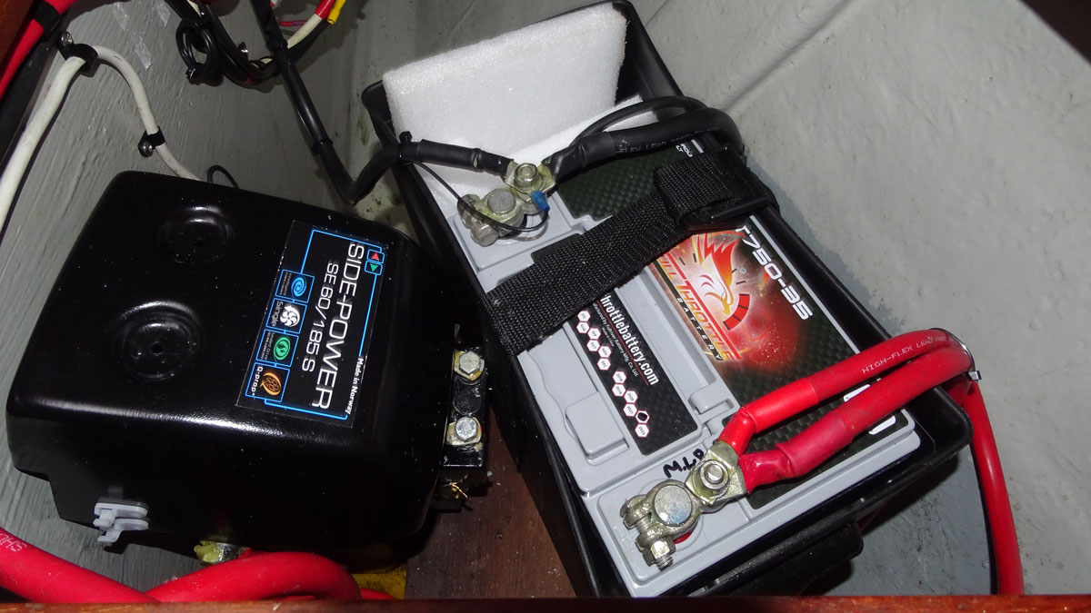
We added a DC-DC charger to charge the domestics from the engine via the starter battery (previously, a defunct diode appears to have fulfilled this role), and two used but serviceable lead-acid batteries which we charged with additional DC-DC chargers.
This gave us 400Ah of domestic batteries spread, bizarrely, across three banks, with the starter battery making up our fourth bank.
I quite enjoyed seeing the surprised faces when we referred to our four battery banks!
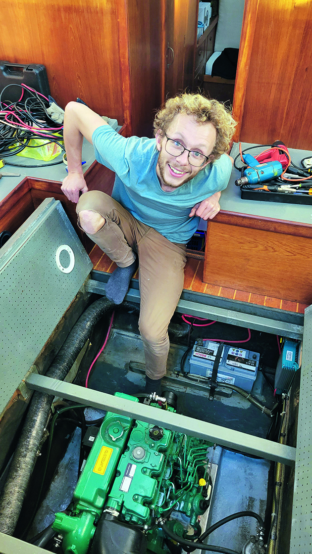
Richard Thomson with his revamped engine bay, now much neater
Saving power
Adding a solar anchor light with integrated battery and light sensor helped reduce power draw during hours of darkness.
Three Victron DC-DC chargers (total cost under £500), the solar anchor light (£30) and two used but free batteries got us on the water and saw us through until we lifted out in November 2023.
Many cruisers have been shocked that we managed six months on 240W of aged solar and an aged 400Ah lead-acid domestic bank.
It certainly took effort; switching things off religiously when not in use, charging devices when the engine was running, and switching from one ‘bank’ to another.
But of course, it can be done and it certainly taught us to be frugal with our energy consumption.
However, by November 2023 it was clear the batteries were toast; they were regularly showing 11.6V in the morning and the fridge would have cut out.
Sometimes we needed to run the engine at anchor to charge. And so, in early 2024, new batteries rose to the top of the list.
Our experience had taught us we had been surprisingly close to managing our electricity needs, but we were keen to add a second fridge and didn’t want to be running the engine at anchor.
Battery upgrade
After much research, we settled on lithium-iron phosphate (LiFeP04) batteries, rather than some form of lead-acid chemistry.
This is increasingly popular on boats, so I will say only that we’re happy we did and very briefly sing the praises of the LiFeP04 chemistry: LiFeP04 is extremely stable (read safe – it’s a different lithium-ion chemistry than found in a phone or electric car. Those occasionally do spontaneously combust! LiFeP04 does not).
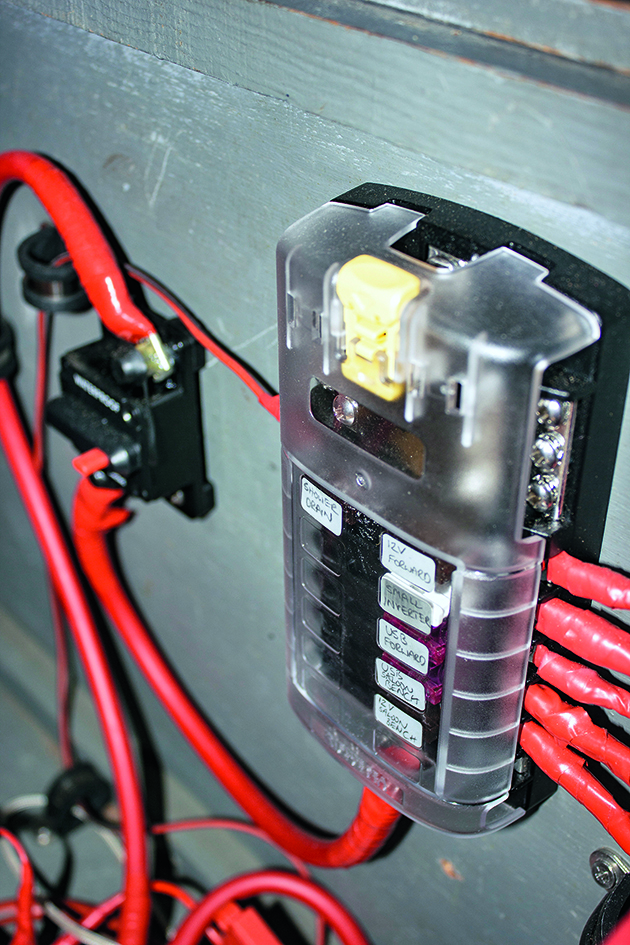
Loads are all fused and labelled
It is more efficient in charging and discharging than lead-acid chemistries and takes up less space and weight for the useable energy provided.
Lastly, LiFeP04 has a longer life expectancy than lead-acid chemistries, so you should recoup the original outlay provided you keep the boat for a few years.
However, they need specialist chargers and certain protection mechanisms – more on that later.
We bought four 100Ah LiFeP04 batteries from a company called LiTime.
These were well reviewed and cost around £950 in total, which is certainly on the budget end for LiFeP04 – around 18p per Wh.
Our batteries have an internal BMS (battery management system) which controls the charge and discharge process, as well as an overtemperature and low-temperature sensor, but have no display or Bluetooth, which higher-end options may offer.
We decided instead to spend our money on high-quality chargers, battery monitoring, a proper master fuse and an additional external temperature sensor.
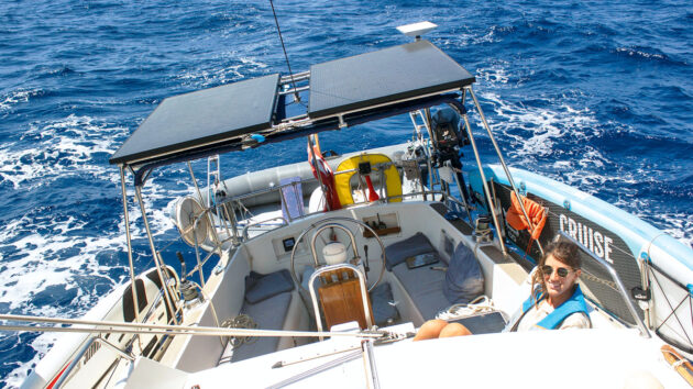
Before returning to Namika we also bought two large domestic, rigid split cell solar panels, each rated at 360W and measuring around 1m wide by 1.7m long.
We chose these as being closest in dimension to our existing, underutilised bimini structure which I intended to modify to become a solar arch.
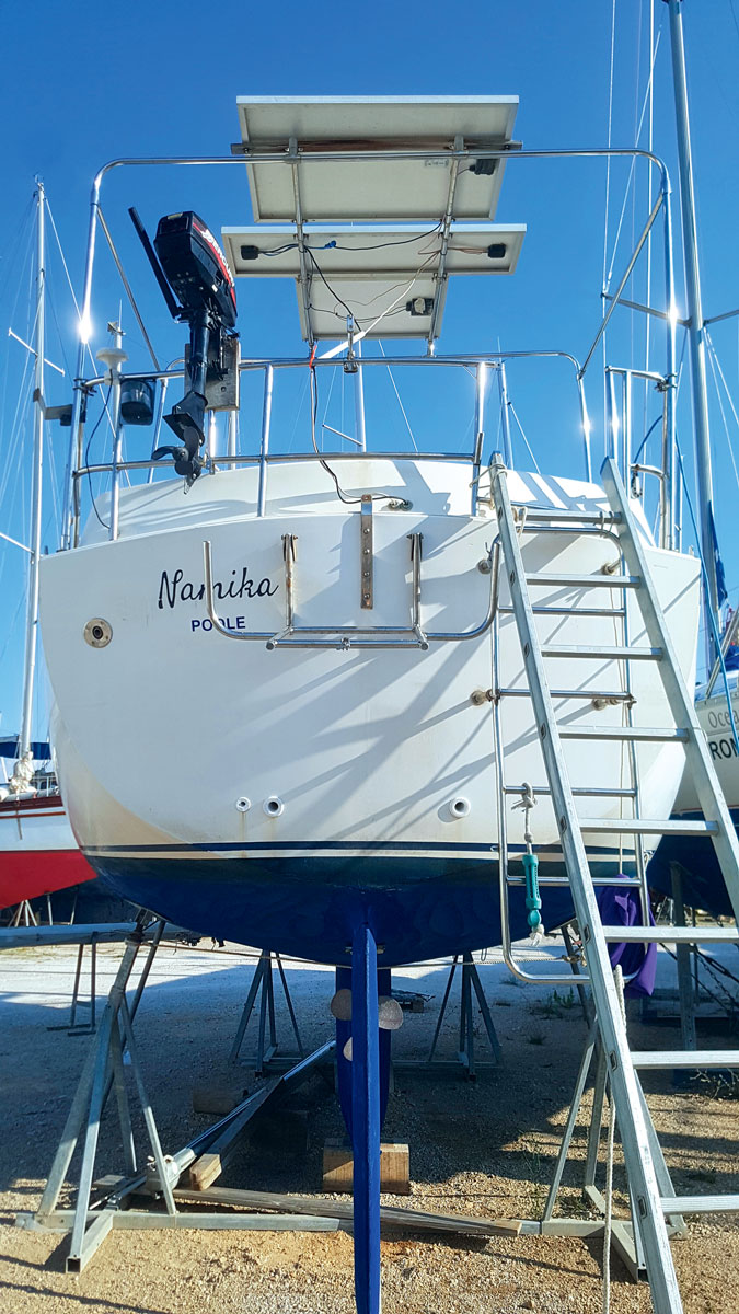
The existing bimini structure carried three small solar panels but was underutilised and a little wobbly
Solar arches are expensive, and there were big savings to be had by modifying the existing structure rather than having one custom-built.
Split cell panels are great because they increase the voltage output per panel, meaning thinner wire runs to the solar charge controller.
They also respond better to partial shading, which is a frequent problem due to masts and rigging.
Buying domestic panels directly from wholesale meant we had to collect them ourselves, but they cost just £200 in total, which is frankly a bargain.

The existing bimini frame was modified and strengthened using stainless steel tubing and connectors to create a supporting frame for solar panels. Triangulation is provided by running to the toerail and tensioning with turnbuckles. The structure is now extremely rigid
Flexible panels are a popular alternative and they are certainly easy to install.
However, they are generally more expensive, lower in efficiency and have. a shorter life span than rigid panels.
We had three Victron DC-DC chargers as a result of our rather piratical workaround in 2023.
Now, we planned to use the two 30A chargers to charge the domestic bank from the alternator via the AGM (absorbed glass mat) starter battery.
Our stock alternator is rated at 115A; as I understand it using half of that – 60A – is optimal for longevity, so a total of 60A would be perfect.
We also planned to use the 18A charger to charge the starter battery from the domestic bank.
This helps prevent the starter battery from going flat, and acts as a low-level draw on the LiFeP04 bank when leaving the boat over the winter – desirable to prevent them from sitting at full charge.
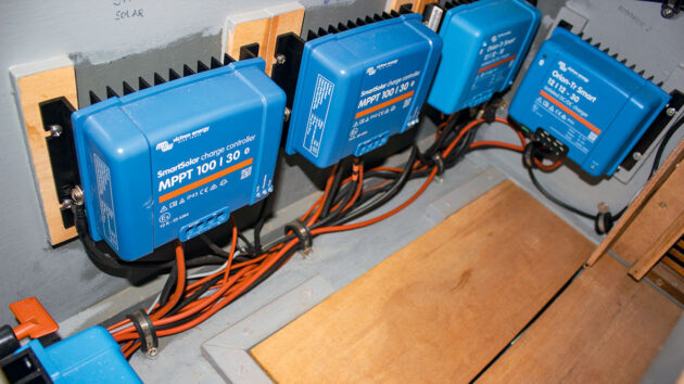
We also bought two Victron 100 30 MPPT solar charge controllers (around £220 in total), one for each panel. 360W per panel at a nominal 12V yields 30A, so one 30A charger per panel was fine.
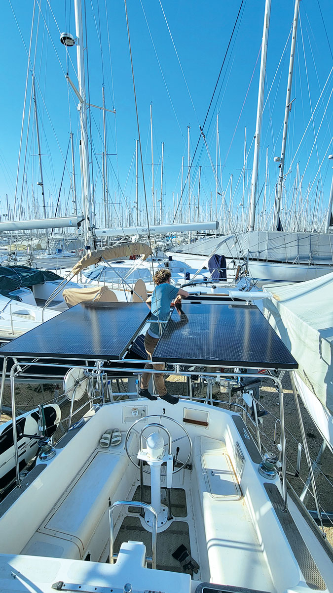
Mounting the solar panels. The bimini still fits underneath
Keeping the panels separate is a little more expensive than wiring them together but prevents shading on one from limiting the output of the other.
Given the backstay would run between our two panels, there is nearly always shading on one of them.
It also offers redundancy; if one panel, wire, or charger fails the other would still generate independently.
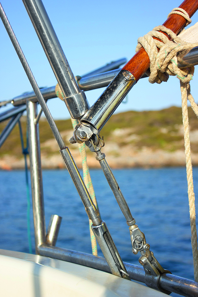
Fore and aft triangulation is provided by attaching to the pushpit and tensioning with a turnbuckle
Choosing split cell panels with their high voltage output allowed us to separate our panels. Higher voltage means lower amperage, and therefore thinner wires.
Our panels have an Open Circuit Voltage (VOC) of around 40V, which is only 9A (360W panel divided by 40V equals 9A) before it gets to the solar charge controller, low enough to run happily through 4mm2 wire for up to 15m.
Thinner wire is cheaper and easier to thread through the boat.
If that open circuit voltage had been lower, we might have had to wire the panels in series or pay for and wrestle several metres of much thicker wire.
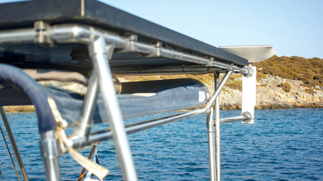
The Starlink dish is held clear of the solar panels. Space between the panels and the bimini canvas stores paddles and windsurfer parts
The Victron chargers conveniently feature Bluetooth allowing them to be easily configured and monitored from your smartphone.
This also allows devices to communicate over what is known as the VE Smart network, meaning charge and discharge data, battery voltage, current and temperature are shared between devices.
This optimises charging and adds a second layer of protection alongside the internal BMS within the batteries.
We used marine-grade rather than automotive wire, and I would recommend doing so. While slightly more expensive, it is safer as it is more corrosion-resistant and flexible.
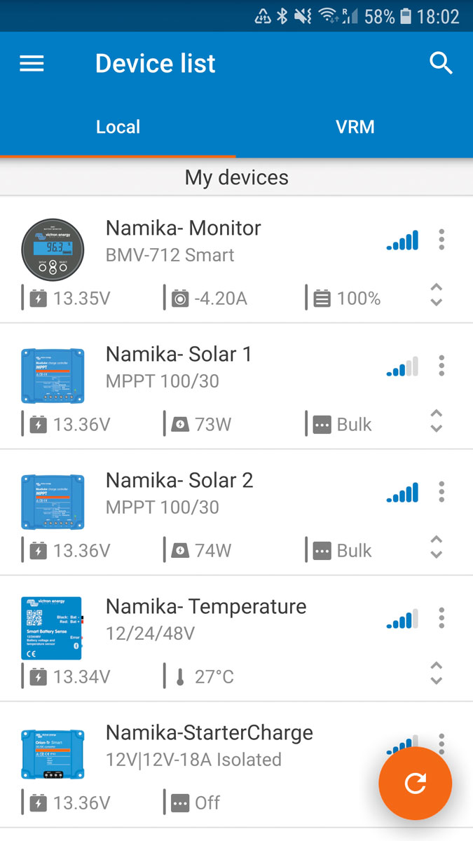
The Victron App allows you to see loads, charge, battery temperature and quite a bit more
Our last components were the Class-T master fuse (the recommended type for LiFeP04 batteries due to their high amp-interrupt rating), sundry circuit breakers and fuse holders, the Victron BMV 712 battery monitor and temperature sensor.
We weren’t quite sure where to locate everything, but I was keen to move the batteries from the engine bay.
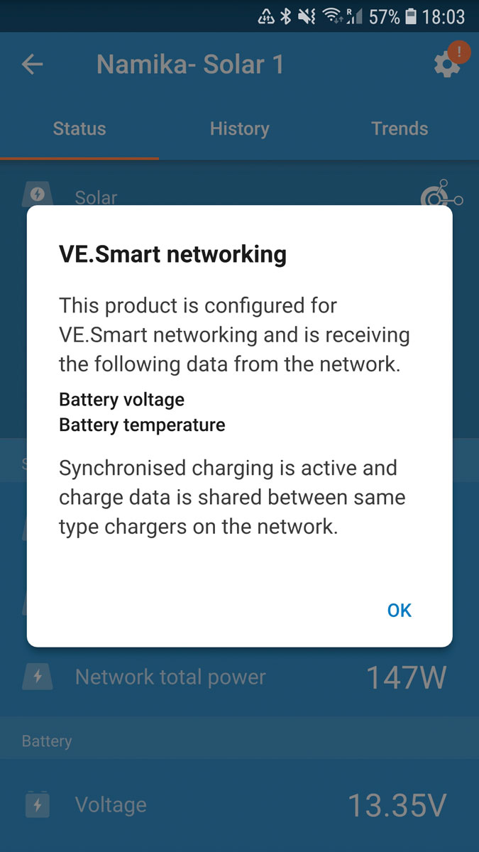
The app also allows devices to communicate so the chargers ‘know’ battery voltage and temperature and can act accordingly
Hard work begins
Upon returning to the boat in early 2024, I disconnected the old batteries, solar panels and shore power charger so there was no power on board.
Then, little by little I gradually picked apart the bird’s nest and followed every wire back to the appliance it served, stripping out anything that was defunct and labelling wires which could be kept.
After some exploration, I found the four new batteries fitted nicely in a locker under one of the saloon benches.
This was a perfect spot, away from the engine, in a central, dry, protected space, just above the waterline.
There was also an adjacent locker where I could fit the chargers.
I aimed to divide everything between these two spaces, keeping the batteries, fuses and circuit breakers in one ‘positive locker’.
The only exceptions are the four negative terminals of the batteries and their common negative stud, which I painted in liquid electrical tape and physically isolated with wood.
The adjacent ‘negative locker’ housed the shunt from the battery monitor, main negative bus bar, and chargers.
While the chargers also have positive terminals, these are completely shielded; it’s never possible to completely separate positive and negative spatially.
However, I was pleased with how well my attempt had worked. A short circuit is now near impossible.
The batteries, both charging circuits, and all distribution points can also be independently isolated using switches and breakers.
This means we can shut down parts of the system without turning everything off; in the event of a serious failure in a charging source or even a battery, we’d still have power for instruments such as the depth sounder and autopilot.
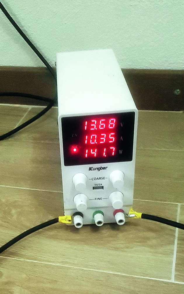
Top-balancing each battery using a bench power supply to help prolong battery life
We could even shut the domestic batteries off and still run up to 60A of loads from the solar panels in daytime, or a further 60A when the engine is running.
Arranging everything so close together allowed us to keep most wiring runs extremely short.
Except for a run aft to secondary bus bars (around 3m each way), the negative ground to the engine, and the existing run forward to the windlass, I barely had a run of thick wire longer than 1m.
This is extremely energy efficient, but also financially efficient because copper is not cheap.
Shorter runs also allowed me to cut down and reuse existing wires, which saved more money.
The wire I did buy cost between £600 and £800; not bad for an almost complete rewiring.
Taking a little time to plan and keeping everything close together undoubtedly saved us a lot of money; we could easily have spent two or three times that on wire alone.
Remember, the thickness of the wire must be matched to the expected load and be thick enough to carry the current required to blow the fuse.
Wire thickness also needs to increase for longer wiring runs.
If unsure, a great place to start is the Blue Sea Systems DC wire sizing chart.
The last key part of the project was the solar arch.
I intended to build a frame above the existing bimini structure to carry the panels.
The original was a little wobbly and we’d be adding extra weight and a fraction more windage, so we wanted to strengthen it.
Not being a stainless steel welder, I decided to use stainless tube connectors; this allowed me to adapt my design as I went along.
We bought around 30 connectors and 10m of stainless steel tubing.
An angle grinder made short work of the cutting, and the horizontal frame for the panels slotted together quite easily; lengths from the upper frame were run down to the pushpit and toe rails to provide triangulation.
We used turnbuckles for these triangulating lengths which we tensioned down so that our once wobbly bimini structure is now extremely rigid.
We added Loctite before tightening the grub screws so they shouldn’t rattle loose, and for the triangulating lengths, I drilled the tube so that the grub screw had something to bite against before tensioning.
An extension on the port side holds the Starlink dish, and the space between the bimini canvas and the solar panels securely stores three paddles, two wishbones and a mast for the windsurfer.
The costs were around £350 for the tubing and £350 for the connectors.
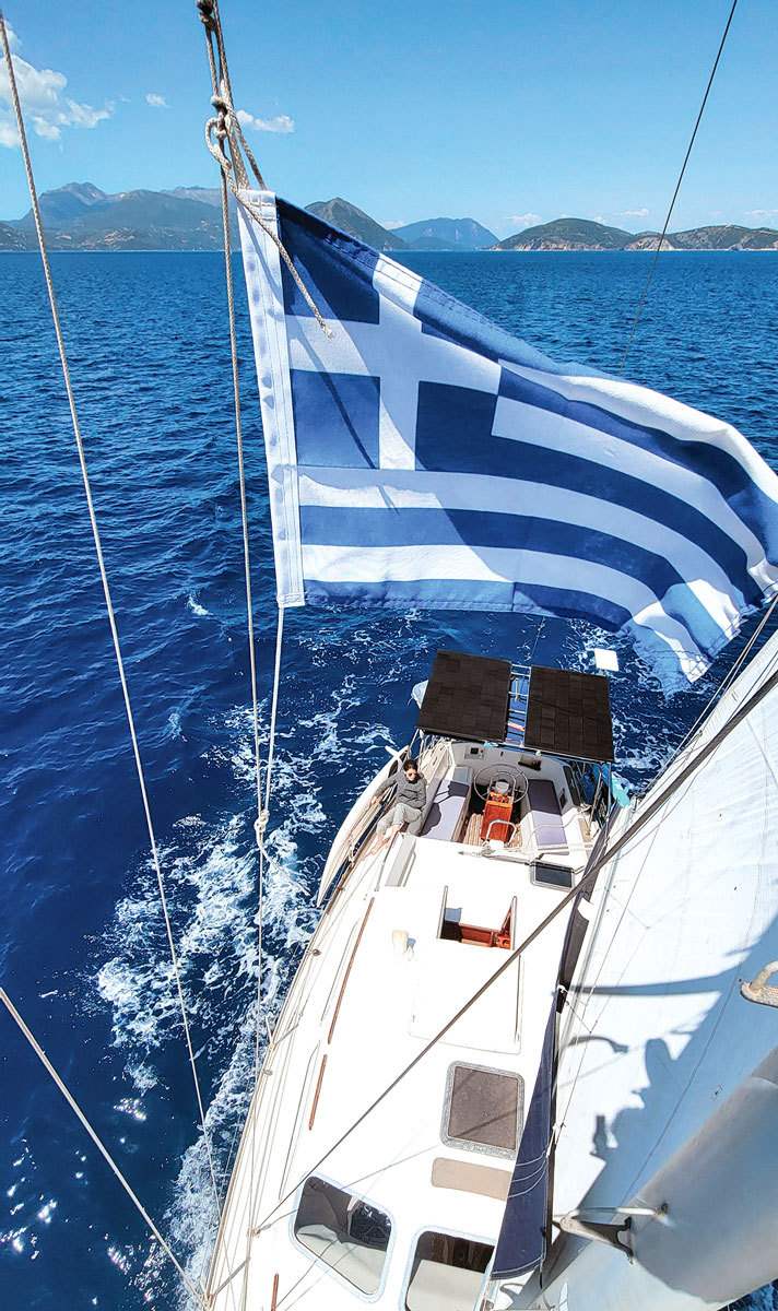
Namika is a comfortable deck saloon cruiser. She’s most at home out on open water and is surprisingly quick
Finishing touches
A few days before DC-Day, I used a bench power supply to charge the batteries individually to 100%, known as top balancing.
I then installed a common positive and common negative stud to which I connected the battery terminals.
The wire running from this stud to the loads and chargers must be thick (we used 95mm2), but the wire running from each battery to that stud can be thinner
as it’s only taking a quarter of our overall loads (we used 35mm2).
The trick is to cut all your wires for connecting each battery terminal to the common stud to exactly the same length so that the wires have exactly the same resistance across them.
After crimping the wires we used a multimeter to check that all the positives had the same resistance, then checked the negatives too.
We then left the four batteries connected for a couple of days without any loads or charging source so that any minute discrepancies in state of charge (SOC) were evened out, known as passive balancing.
The idea here is that the batteries start equally charged and, by keeping the resistance exactly equal, should remain so.
Thus, all batteries work as hard as each other which should prolong their collective lifespan; with luck, they’ll never go out of balance.
An electrical engineer friend reviewed our work before we switched on.
He asked me to start with the batteries and explain everything we had done, drawing a diagram from my description to check my logic.
If possible, a peer review is a great idea, even for the more knowledgeable and confident, because we can all make mistakes.
Fortunately, our friend had no bones to pick with the installation and so, gingerly, we switched on… It worked!
Rationally, I thought it would, but my previous, less-informed self could hardly believe it.
It all worked!

Richard Thomson’s simplified overview of Namika’s new DC system
Looking back, I still can’t quite believe that the person whose electrical experience a year or two before amounted to touching an electric fence and changing a lightbulb had now completely rewired our floating home, built a solar arch, replaced batteries and solar panels, and chosen all the components to do so.
Eight months later we’ve had no power issues and, frankly, have much more power than we currently use.
The power that could be generated by our alternator when the engine is running is rarely used because the batteries are fully charged within an hour of the sun coming up.
The various chargers are housed in a locker close to the batteries, along with the main negative bus and the shunt
The batteries have only dipped below 75% state of charge (SOC) once overnight.
We’ve not yet decided if and how we may want to use the extra power in the future, but if desired (and our budget allows), I’m confident we could run a watermaker, electric water heater, washing machine and induction hot plate for up to one hour of electric cooking, though obviously not all at once.
That’s the power of LiFeP04 batteries, large modern domestic solar panels, and the Mediterranean sun.
Nevertheless, good results can be achieved in the UK with solar, and installing a larger alternator is a great way to generate power quickly where the sun is a little less reliable.
An hour of motoring every day or two with, say, a 200A alternator, coupled with a little solar (or wind) generation should provide ample power for most creature comforts on even quite cloudy days.
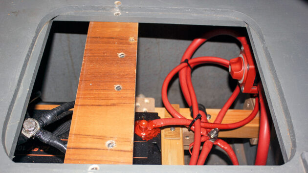
Positive and negative studs are physically isolated by wooden bracing which stops the batteries moving and prevents an accidental short circuit
What it cost
Our electrics project took around two weeks to install. We did all the work ourselves, and total costs came to roughly £4,000, as shown in the costs breakdown panel (right).
That’s certainly a lot of money; the sort of money we do not spend lightly.
However, we now have complete electricity independence, and the system should be good for at least 10 full years of continuous use, probably longer.
That’s £400 a year for full-time liveaboards; quite a bit cheaper than the average UK household electricity bill!
It’s also worth mentioning that I know plenty of cruisers who have paid multiples of this figure just to have parts of the above project done; a professionally built, welded solar arch can cost several thousand pounds alone.
Does this make sense for the weekend sailor?
Probably not. It also doesn’t make sense if you plan to sell the boat in a year or two.
However, if you’re lucky enough to have found that stray old boat you want to keep sailing and if you’re fortunate enough to spend weeks or months on board then I think it’s a great investment.
The cherry on top? Doing the job ourselves allowed us to take the time to build it exactly as we wanted, and it was incredibly rewarding.
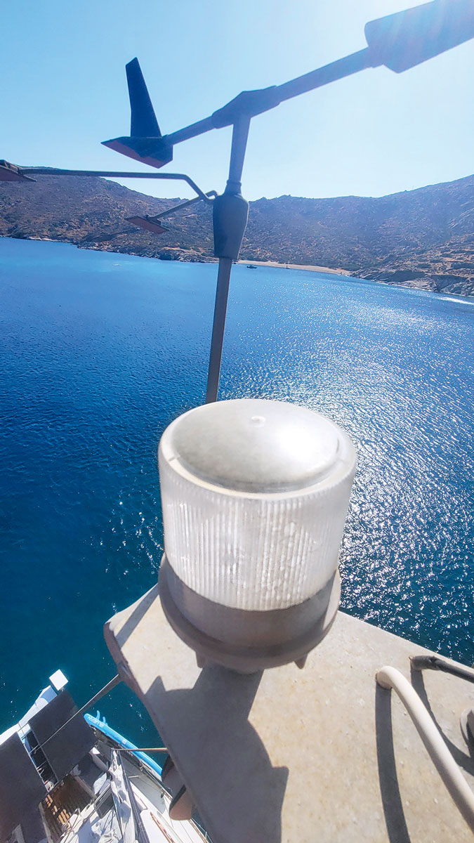
This £30 solar anchor light turns on automatically when it gets dark and has its own internal battery – a big help in reducing overnight power consumption
Lessons learned
If you’re just starting with a new-to-you boat, try to stick it out with the existing set-up for at least a few months, ideally a year.
That way, you’ll see how it performs (especially as the seasons change) and learn how much – or how little – electricity you need before potentially spending lots of money.
You’ll also be better informed about any extra comforts you may want to install, like a watermaker or induction hob, and their electric loads.
You want to broadly match your ability to generate electricity with your ability to store it. This is especially important if your generation is primarily via alternator (short periods of fast charging) or wind (irregular, slower generation).
If you are primarily relying on solar (regular, slower charging), I think having comparatively more solar generation and less battery storage is cost-effective and will mean you’re not always fighting to keep your batteries charged.
You’ll be in the nice position of having loads of excess power during the day and can essentially run whatever you want (within reason).
As the panels age and lose efficiency, you’ll not immediately lose your perfect charge-storage balance as you had more solar than ‘necessary’ to start with.
Balance your batteries before switching on, and connect each positive battery terminal to a common positive stud, the same for the negatives, making sure the lengths and resistances across the wires are the same from each battery.
This should help keep the batteries balanced and prolong their life.
Electrics isn’t rocket science, and by choosing to get your hands dirty you’ll have the benefit and satisfaction of understanding your system perfectly; you can also take the time to locate everything exactly where you want it.
All powered up! Namika on passage, doing seven knots and with more electricity than Richard and Maxi currently know what to do with!
Ed’s note: A survey was carried out for Richard’s insurance company, which noted ‘the electric installation was found to have been done to a professional high standard’. Most insurance companies will want a full inspection to be done before agreeing to insure any changes to your boat. Remember, always consult your insurance company before making significant changes like this to your boat as it could invalidate your insurance.
Costs
- Batteries (4 x 100Ah LiTime LiFeP04) £950
- Solar panels (2 x Longi 360W) £200
- Solar chargers (2 x 100 30 Victron MPPT) £220
- DC-DC chargers (2 x 30A, 1 x 18A Victron chargers) £500
- Battery monitor (1 x BMV. 712 Victron monitor) £120
- Battery temperature sensor (1 x Victron Smart Sense) £30
- Wiring, lugs £600-£800
- Circuit breakers, fuses, fuse holders, bus bars £500
- Stainless steel tubing £350
- Stainless steel tube connectors £350
About the author

Richard Thomson learned to sail on the west coast of Scotland. A spell of teaching and skippering in the US, Caribbean and Mallorca followed. He now works as a sailing and history illustrator. In 2022, Richard and his wife, Maxi, bought the Trident Marine Voyager 38 Namika and are currently cruising in Greece with their dog.

Understanding electrics: insulating & signal wire connectors
Oliver Ballam and Pat Manley demystify boat electrics and explain various types of electrical connectors and their uses on board
Boat battery bank and electrics upgrade
After mid-Atlantic battery failure, John Willis decides it’s time to upgrade his battery bank and electrics

Boat battery care: the do’s and the don’ts
Stuart James of Predator Batteries shares his expert tips for achieving optimum battery performance on board your boat

How to tidy up boat electrics? Ask the experts
PBO reader John Anderson writes: “I have the mast out of my 30 year old Malo to solve an in-mast…
Want to read more practical articles?

A subscription to Practical Boat Owner magazine costs around 40% less than the cover price.
Print and digital editions are available through Magazines Direct – where you can also find the latest deals.
PBO is packed with information to help you get the most from boat ownership – whether sail or power.
-
-
-
- Take your DIY skills to the next level with trusted advice on boat maintenance and repairs
- Impartial in-depth gear reviews
- Practical cruising tips for making the most of your time afloat
-
-
Follow us on Facebook, Instagram, TikTok and Twitter