Tony Davies shows how he rebuilt the helm position and instrument panel on a 1970s Reinell V-204 sports cruiser
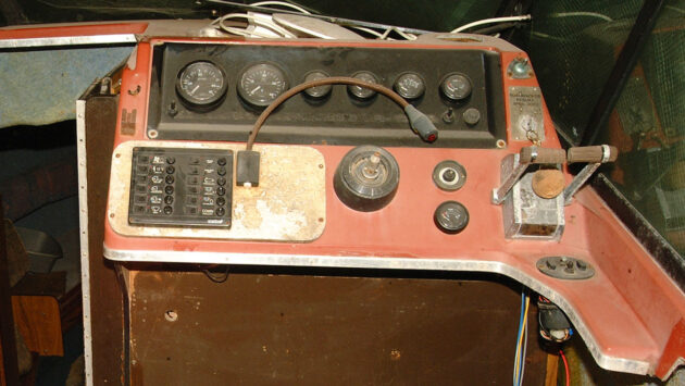
This American Reinell V-204 built in 1978 was in a pretty sad state as you can see.
One area I particularly like to make a fuss of is the helm position and instrument panel, as that’s where a lot of time is spent when under way.
Let’s begin with a look at the sports cruiser when I got her back to the shed.

The American Reinell V-204 needed some serious work! Credit: Tony Davies
The boat came with standard trim. Overall she wasn’t very pretty even when she came out of the factory all those years ago, although I found the shape quite appealing and she had avoided the era of the extended ‘beak’ on the bow.
The helm area was particularly outdated and was going to need extensive reworking to bring it up to an acceptable modern standard.
Boat instrument panel and helm refit: step-by-step

Credit: Tony Davies
1. I started by removing the half-bulkhead, instruments, controls and panels. The heads compartment on the other side of the helm half-bulkhead housed much of the electrics (including 240V) so this was ripped out.

Credit: Tony Davies
2. With the top locker in the heads compartment removed, I had easy access to the electrics, instruments and controls.

Credit: Tony Davies
Once everything had been cleared away, I had a relatively blank canvas from which to start the rebuild.

Credit: Tony Davies
3. I started by replacing the heads side panel and the half-bulkhead between the helm and heads and closing off the open area underneath the instrument panel. I also infilled the holes in the helm main panel. (Ignore the helm pump and pipe-work as that is another story!) Each ply infill panel was epoxy coated before bonding in with West Epoxy and bi-axial cloth.

Credit: Tony Davies
4. The only modification I wanted to make here was to remove this small corner infill which was cut away very easily and cleanly using a multi-tool with a bi-metal blade.

Credit: Tony Davies
5. I then built a locker to house the circuit breaker board and main switches.

Credit: Tony Davies
Once complete, I spent a lot of time with a long board and sander filling and fairing until I’d achieved a reasonable finish. It was then sprayed with epoxy primer.

Credit: Tony Davies
6. Remember the original instrument panel which was one of the first things to be removed? This is made from a moulded resin material and being a perfect fit for the hole it came out of, was worth retaining. So I roughened the back surface and applied a single layer of bi-axial cloth and West Epoxy to close off the original holes.

Credit: Tony Davies
7. There were also various damaged areas that I reinforced in the same way. It was then turned over and the original holes filled and faired with Jotun epoxy fine filler.

Credit: Tony Davies
8. For the next step, I bought a leaf of real burr walnut from a supplier on ebay and bonded it to the panel using a strong contact adhesive. I applied five coats of polyurethane varnish on consecutive days which gave sufficient film thickness to begin lightly sanding to take off the visible roughness. I repeated this process twice more until I had a slightly glassy finish.

Credit: Tony Davies
9. I’d already planned what instruments I would have on the panel and drawn out a plan for cutting the apertures. I used a crosshead screwdriver to create marks for the centres of the instrument holes.

Credit: Tony Davies
10. Next, I moved over to the pillar drill with a brand-new hole saw to begin the cutting while carefully avoiding any slips!

Credit: Tony Davies
11. The next step was the aperture for the engine warning lights bar, using the trusty multi-tool again and being even more careful about slipping.

Credit: Tony Davies
12. The final cutting job was to open up the slots for the row of switches and the apertures for the Garmin instrument units.

Credit: Tony Davies
13. The apertures on the front of the boat instrument panel were closed off with masking tape to avoid any spills while I undertook the next step.

Credit: Tony Davies
14. In this step, I sealed the edges of all the cut-outs with epoxy resin to stop moisture from finding its way beneath the walnut veneer.

Credit: Tony Davies
15. I could now begin one of the most satisfying parts of the job – fitting the new instruments and switches into the panel.

Credit: Tony Davies
16. With all instruments fitted, I sat back and admired it all for a few minutes. I decided that although the walnut panel wasn’t quite up to Rolls Royce standards it wasn’t too bad!

Credit: Tony Davies
17. Back to the helm position and three coats of Jotun Megagloss applied wet on wet finished the build work.

Credit: Tony Davies
18. Once the boat instrument panel was installed, I made up a stainless steel frame to cover the edges which set it off nicely. I also began adding other instruments including the chartplotter and chain counter.
Boat electronics repair: How to fix your boat’s instruments
If you can solder it’s always worth taking things apart and having a go at repairing them as a last…
Electronic repair tips and tricks for boat owners to fix instruments
Often the causes of electronic failures are not electrical at all. The environment on a small sail or power boat…
How to repair instrument gauges
Every boat has a number of gauges for water, fuel and waste tanks. Every so often, one of them will…
Instrument panel from an Ikea tablet stand
Last year, having put a couple of instruments on my Christmas list – a battery monitor and a Navtex receiver…
How to calibrate your boat’s speed, depth and wind instruments
There are two main methods for calibrating your boat’s speed instrument: The measured mile or the SOG check. The simplest…
Want to read more practical articles like Boat instrument panel and helm refit: step-by-step?

A subscription to Practical Boat Owner magazine costs around 40% less than the cover price.
Print and digital editions are available through Magazines Direct – where you can also find the latest deals.
PBO is packed with information to help you get the most from boat ownership – whether sail or power.
-
-
-
- Take your DIY skills to the next level with trusted advice on boat maintenance and repairs
- Impartial in-depth gear reviews
- Practical cruising tips for making the most of your time afloat
-
-
Follow us on Facebook, Instagram, TikTok and Twitter


