
Mark Ryan tackles a job to avoid ‘killing your engine and perhaps your crew...’
The small amount of wind we had died away as the sun sank toward the horizon.
Of the 15 hours of the passage so far, only three had been under sail, and even then, we’d not achieved a passage-making speed.
We were on the delivery trip back from Poole, where I’d purchased Mirage, a beautiful and spacious 2002 Bavaria 40, to the River Medway.
This was my first meaningful passage in the new boat, so the chances of any sleep off watch that night were slim.
As I went below, I noted with the engine humming back into life, the faint smell of exhaust, which concerned me, but I reassured myself as the inky black of night descended over Dover, it was likely just a hot engine smell.
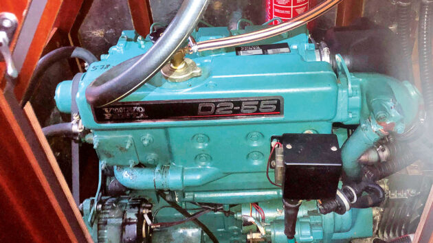
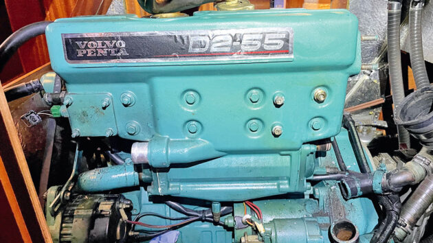
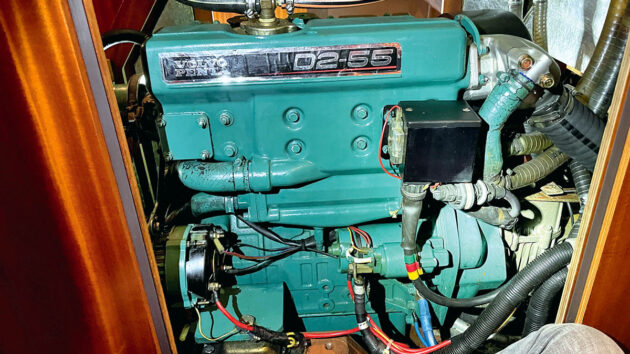
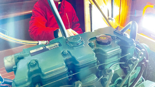
Mirage’s Volvo Penta D2-55A gleaming. Credit: Mark Ryan
The rest of the passage passed uneventfully, however, that whiff of exhaust fumes bothered me.
When I’d purchased Mirage earlier that year, I had marvelled at her engine.
The big Volvo Penta D2-55A gleamed green, without a visible spot of rust, oil or dirt.
My previous boat, a 30ft Albin Ballad, had a raw water-cooled Yanmar 2GM20, and while I had a lot of experience with that engine, my knowledge of indirectly cooled engines was practically nil, so I relied upon the pre-purchase survey giving it a clean bill of health and a Volvo Penta accredited engineer giving it a very quick once over before we tramped home from Poole to the River Medway.
As winter approached, keen to understand the engine and service it myself, I did as much reading as I could around the engine.
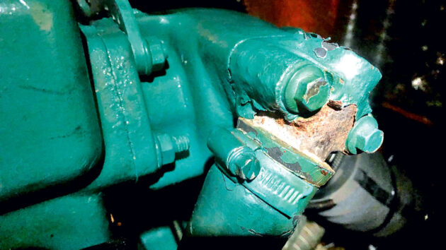
One sobering post on the fount of knowledge that is the Bavaria Owners’ forum urged owners to check their wet exhaust’s water injection elbow as, if it became blocked with rust or scale, the heat exchanger would corrode quickly at the flange between the exhaust elbow and the heat exchanger and leak toxic gases into the boat.

The only part of my new engine with any visible external rust was this water injection point on the exhaust elbow, so over winter I resolved to take the elbow off and inspect it and see if this was the source of the exhaust smell.
With no notion even of what a heat exchanger was (coming from my raw water-cooled engine background), I set about swotting up.
What is a heat exchanger? The clue is, as ever, in the name.
On an indirectly-cooled engine, the raw seawater only ever flows through the heat exchanger and doesn’t flow through any part of the engine block itself.
The raw seawater is pumped in through the raw water pump, much as with my old directly-cooled engine, however rather than circulating that water through the engine, it passes through bronze tubes that pass through a chamber where it cools down the closed freshwater system, once the engine is up to temperature.
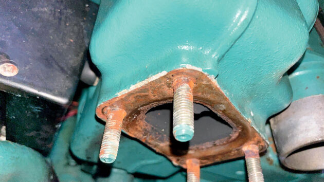
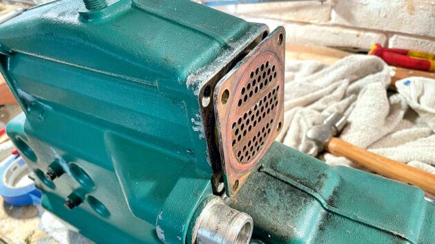
Exhaust elbow flange with heat exchanger. Credit: Mark Ryan
There is a separate freshwater circulating pump that moves this coolant around the block and through the heat exchanger.
There is a thermostat that will only circulate the cooling water through the heat exchanger once the engine is up to temperature to help the engine get to operating temperature as quickly as possible.
This means only clean water with coolant and rust inhibitors circulates around the engine itself, and the raw water doesn’t.
The heat exchanger is made of aluminium as this has a high thermal conductivity – the material itself is a key consideration, as you’ll see later on.
What is an exhaust elbow?
The exhaust gasses leave the engine at a very high temperature and exit via the heat exchanger.
Under load, this can be as high as 400-500°C. The engine reuses the water it has warmed up in the heat exchanger to finally cool the exhaust elbow by injecting this water into the exhaust elbow a little way after the heat exchanger, cooling the gasses and the elbow itself.
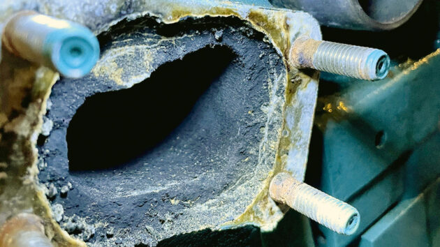
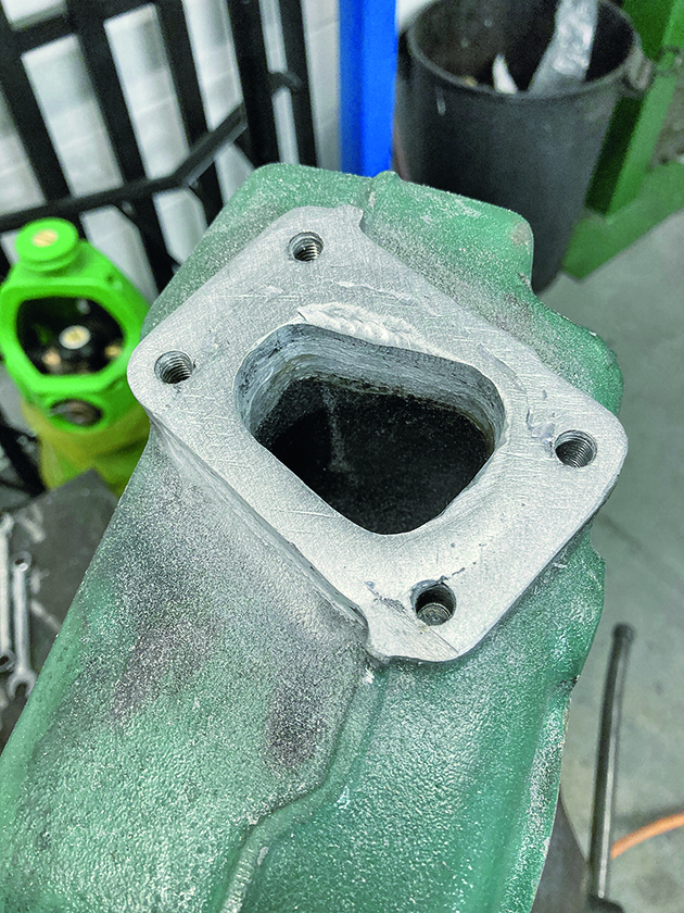
Exhaust elbow flange corroded through, showing where toxic gases were escaping. Credit: Mark Ryan
The exhaust elbow is made from mild steel, with a stainless-steel gasket between the aluminium heat exchanger and the mild steel exhaust elbow, and having all these dissimilar metals so close together, and so close to an electrolyte (the injected sea water) is where our challenges here begin.
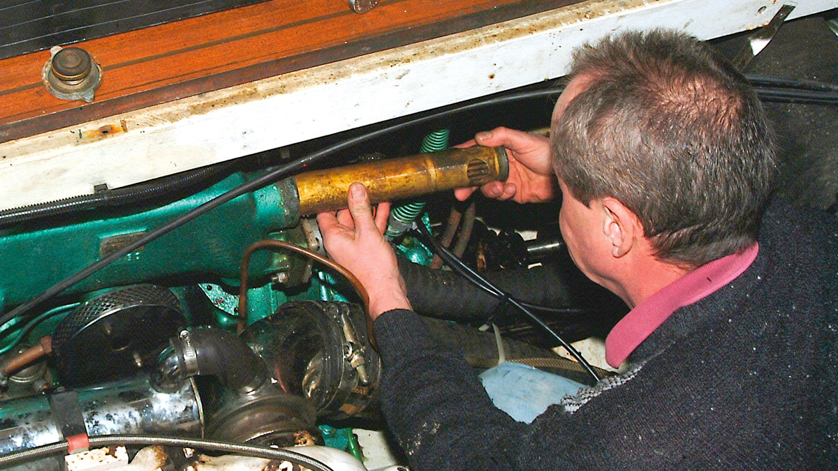
Removing the exhaust elbow
The exhaust elbow on the D2-55A is held on with four nuts onto four studs that stick out from the face of the aft face of the heat exchanger.
In order to remove the exhaust elbow, I had to first remove the air filter box, which is only held on with a jubilee clip and a nut.
I was expecting a fight to get the elbow itself off, however, all four nuts, whilst considerably tight (and that I suspect had never been taken off in the 20 years of the boat’s life) came away without mishap.
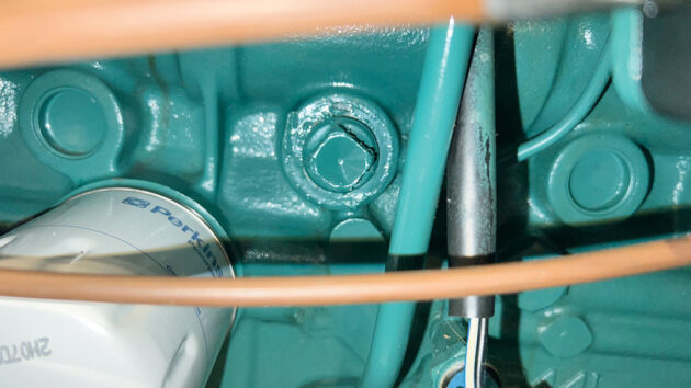
Coolant drain plug. Credit: Mark Ryan
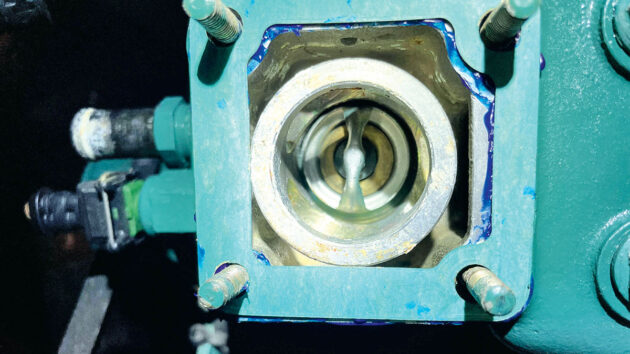
I deposited the exhaust elbow into a bucket for later analysis and inspected the flange where the exhaust elbow connected to the heat exchanger.
It appeared, to my first inspection, flush and fine, so I heaved a sigh of relief that I’d caught it in time.
On closer inspection, however, it became apparent that the flush surface was just the stainless-steel gasket. I prised the gasket away and, to my horror, the face of the heat exchanger had been eaten away to the point where at its lowest point, out of view, it had corroded right through and had been leaking toxic exhaust gases straight into the aft cabin where my crew had slept on the return passage from Poole.
At first, I contemplated filling the flange with a two-part epoxy aluminium filler, however, this is only rated to around 200°C.
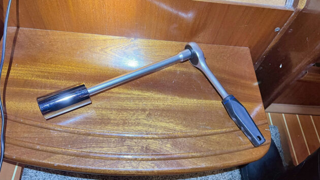
Universal socket to fit the coolant drain plug. Credit: Mark Ryan
Were I in a fix and needed something to get me home, this would be an option, however, I needed something that would be a more permanent solution.
I spoke to Volvo which recommended replacing the whole heat exchanger which would have cost over £3,000, and also it felt like an unforgivable waste, seeing as the rest of the heat exchanger was completely fine.
I concluded I’d need to have the flange welded to build back the surface, and then to have it machined flush once again.
Aluminium’s properties of good thermal conductivity, which make it such a great material for a heat exchanger, also make it notoriously difficult to weld as heat will quickly spread across the heat exchanger.
Added to that, aluminium has a very low melting point, meaning the dissipating heat can warp or melt the exchanger during the welding process – so it’s a job for the experts.
One problem at a time, the first job was to somehow get the heat exchanger off the engine!
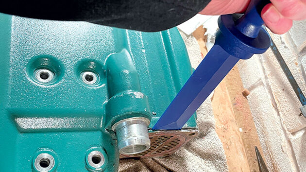
Heat exchanger removal
As the heat exchanger is part of the closed freshwater cooling circuit, the first thing you need to do is drain the coolant.
On the D2-55A like mine, there is a big drain bolt on the starboard side of the engine that is not a hex nut, but a square nut.
None of my imperial or metric spanners or sockets fitted it adequately, and it was exceedingly tight, suggesting it must have been many years since it was last removed.
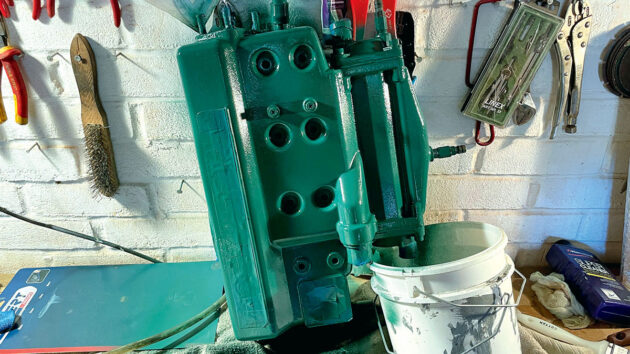
Heat exchanger with all connections removed. Credit: Mark Ryan
I ordered a large universal socket that locked easily onto the nut and using my long breaker bar, the nut started moving and finally came out.
The coolant dumped itself into the sump under the engine, where I used a small 12V pump to empty the coolant into containers so I could dispose of it.
Next, all pipes needed to be disconnected from the heat exchanger.
You’ll find pipes coming from the freshwater pump and the raw water pump, as well as a pipe to the calorifier (the hot water tank).
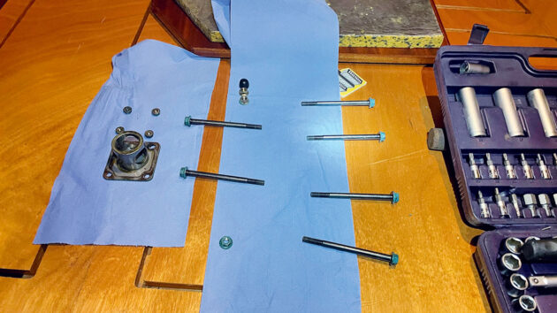
Heat exchanger fastenings. Credit: Mark Ryan
You’ll also need to detach a heat sensor and the electrical box from the aft end of the exchanger.
Once your heat exchanger has all these connections removed, it will just take the six bolts, four nuts and the four nuts holding the thermostat cover plate on, and then it’ll come easily away.
With the high temperatures involved, and the fact dissimilar metals are involved, I had expected removing these fasteners would be tricky, but in reality, it was simplicity itself.
The repair to the exhaust elbow
With the heat exchanger off, it was time to deliver it to a company on the Medway City Estate specialising in aluminium welding called GoToEngineering.
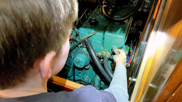
It was Christmas time, and theirs was the sole light still burning on the industrial estate when my eldest, Thomas (8 at the time) and I arrived.
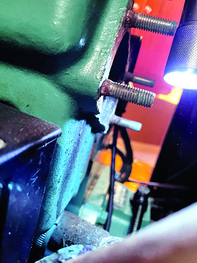
Corrosion of heat exchanger flange revealed after removing the stainless steel gasket. Credit: Mark Ryan
Regardless of the late hour and the season, the engineers welcomed us into their well-organised workshop and took a look at the flange.
After cleaning it up and a quick test weld, they confirmed they would be able to build the surface back up.
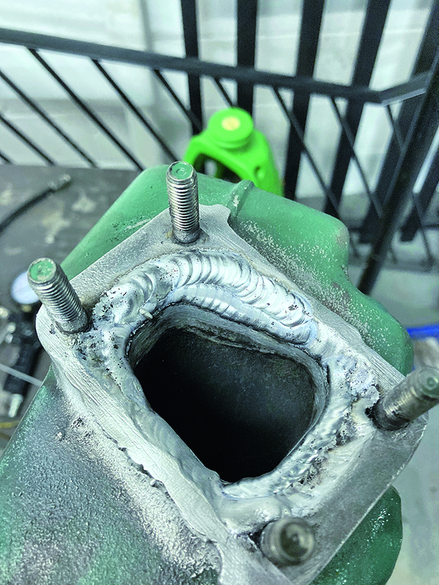
After a few weeks, GoTo Engineering contacted us to report a successful repair.
They had successfully built back up the flange and then, as the heat exchanger wouldn’t fit on their milling machine to mill it flat, used a ‘scraping’ process to get a flat surface to seal onto the gasket.
What is scraping?
I was sceptical of the scratched surface that remained on the flange surface after this scraping process had been completed, however, the engineering company explained the technique to me, and the fact that it had been around since the 1830s when Joseph Whitworth developed it.
Heat exchanger flange after being built back up and then scraped flat. Credit: Mark Ryan
It involves an oily blue substance, known as engineering blue, that is rubbed onto a known flat reference surface (usually made of granite).
The workpiece (in this case, our flange) is rubbed onto that reference surface, which will mark any high points.
These high points are then filed off by hand and the workpiece is rubbed on the reference surface again and the manual process is repeated until finally you will be left with an incredibly flat surface that, in many ways, is preferable to a machined surface.
Pressure testing
Now that we once again had a flush flange, we needed to be sure that the heat exchanger would not leak any gases back into the boat and that the integrity of all three chambers (freshwater, raw water and exhaust gasses) of the heat exchanger had not been compromised.
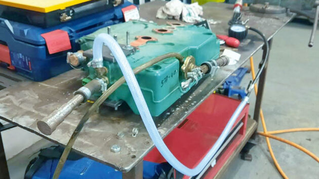
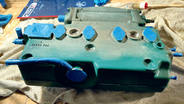
All ports sealed ready for pressure testing. Credit: Mark Ryan
All ports were sealed up and a valve was used to increase pressure inside each chamber of the unit to 15psi to see if it would hold the pressure.
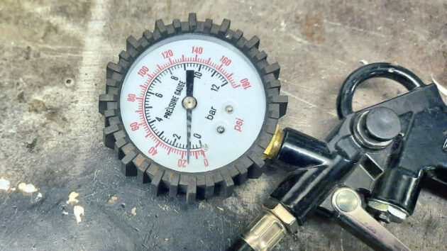
Pressure holding at 15psi in one of the chambers. Credit: Mark Ryan
Thankfully, the pressure held overnight, and I thanked the artisan work of GoTo Engineering.
The skill, ingenuity and dedication found in small companies such as this always astound me.
Extracting the tube-stack and servicing the heat exchanger
Now the heat exchanger was fixed and back in the ‘bat cave’, I wanted to strip it down and take the opportunity to give it a full service.
To cool the water in the closed freshwater system when the engine is running, the raw water is passed through many copper tubes that are stacked together.
A common mode of failure and overheating of these engines is this tube stack getting blocked by weed that has made it past the strainer, or just getting clogged up by salt and scale deposits built up over time.
Four machine screws hold the cover onto each end of the heat exchanger. These are stainless into aluminium so it can be tough getting these off.
With the ends of the stack off, it was evident some weed had made it past the strainer and regardless of our offending flange, it was clear this job was long overdue.
When working with either the copper stack or the aluminium heat exchanger, it is imperative you’re mindful that both metals are very soft and easy to damage.
Both will be significantly softer than any steel tools you have, and any scoring or damage will be hard to repair, so I purchased some plastic chisels to help me split the unit apart (and these have been some of my most used tools ever since!).
The tube stack can only be taken out in one direction, from the aft towards the front, thanks to the lip on the forward end of the stack.
I tried using the plastic pry tools from the front to move the stack out, however, after much bashing of the plastic chisels, there had been little movement.
I moved to the other end of the tube stack and used a piece of softwood scrap and a rubber mallet to try and gently drive the tube stack out, while being painfully aware at all times how delicate (and expensive!) this tube stack was.
Millimetre by millimetre it edged its way free of the heat exchanger until finally it was out.
Now the tube stack was out, I made a warm bath of Rydlyme (which is magical stuff that will melt away any salty or calciferous deposits) and water and cleaned off any of the weed and left it to marinate for a few hours.
Once this process was complete, the tube stack looked as good as new and we were ready to reconstruct the heat exchanger.
The next job was to remove all traces of the cooked-on old paper gasket from the heat exchanger and make sure all the sealing surfaces were flush and clean.
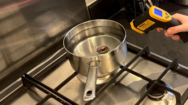
Testing the thermostat is closed at 70°C. Credit: Mark Ryan
Once again, the temptation to use sharp, metal, steel tools to remove these gaskets is very strong.
I gingerly approached the gaskets with a razor blade, scraped horizontally across the face, and then quickly retreated after making some pretty deep gauges in the mating surfaces.
I then invested in some more plastic tools – a plastic scraper!
The interchangeable blades did not last long, however, all the mating surfaces were eventually free of the old gaskets and ready to be reassembled.
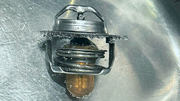
Thermostat open. Credit: Mark Ryan
Testing the thermostat I’d purchased a replacement thermostat anyway, but wanted to be sure the old thermostat was working as expected so I could keep it as a spare.
To test the thermostat, heat up a pan of water to 75°C and plonk your thermostat into the water.
Leave the thermostat for five minutes and check it is still closed. Next, bring the water up to 100°C (boiling) and check the thermostat again to ensure it has opened to at least 8mm.
Extracting the tube-stack and servicing the heat exchanger: step-by-step

1. Removing the tube stack end plates

2. Tube stack end plate removed

3. Tube stack clogged with weed and debris
4. Tube stack removal attempt with plastic chisel

5. Successful attempt – softwood and a hammer

6. Tube stack now free to slide out…

7. … and given a warm bath of Rydlyme and water

8. Exchanger exhaust port with cooked-on gasket

9. Removing old gaskets with a plastic scraper
Respraying the heat exchanger
To complete our rebuild, I taped up all the ports, stickers and mating surfaces, carefully degreasing the unit and lightly sanding it with 320-grit paper, before giving it a couple of good coats of shiny, new engine enamel.
Heat exchanger degreased and masked up ready for spraying with engine enamel. Credit: Mark Ryan
Now the heat exchanger was looking as good as new, all ready to go back onto the boat!
Reassembly and reinstallation
The heat exchanger service kit from the very helpful guys at Parts4Engines has all the correct rubber O-rings and paper gaskets you will need for reassembly.
The kit also comes with a little tube of Blue Hylomar, which is a non-setting gasket sealant and is exceedingly helpful when reassembling.
New paper gaskets installed with a smear of Hylomar on both sides. Credit: Mark Ryan
Paper gaskets should be sufficient to seal all those mated surfaces, however, given the occasional gouge in the mating surfaces where I had removed the old, baked on, gaskets,
I chose to apply a thin smear of Hylomar on all the gaskets around the ports.
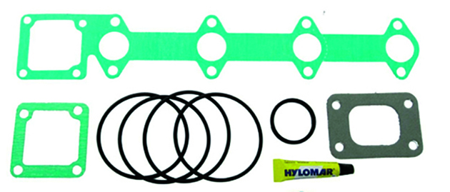
Heat Exchanger service kit
Additionally, to stop any of the pipes from getting set onto the connections, I put a thin smear of Hylomar on all hose ends before reassembly.
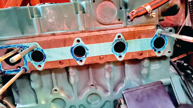
The final job was to fit our new, exciting, stainless exhaust elbow. PartsForEngines includes a composite gasket with their kit that will insulate the stainless exhaust elbow from the aluminium heat exchanger to hopefully prevent this from ever happening again.
Thermostat back in position with new gasket and hylomar. Credit: Mark Ryan
During this process I also replaced the wet exhaust hose as well, as when inspecting this, I found a pinhole in the aft locker that had been gaffer taped up and then had blown through, so my exhaust was actually leaking toxic gasses into the boat from two points of failure!
What was the mode of failure?
Putting so many dissimilar metals so close together, so near a potential source of water, was never going to go well.
The steel exhaust elbow and the aluminium heat exchanger, separated by a stainless-steel gasket is the perfect recipe, with the addition of one key ingredient, an electrolyte (sea water in this case), for galvanic corrosion.
Heat exchanger being lifted back into place. Credit Mark Ryan
All types of metals sit somewhere on a table of nobility. Stainless steel, for instance, is more noble than mild steel, and mild steel is more noble than aluminium.
The lower down the table of nobility (more reactive), the greater the voltage when placed in sea water, the higher on the table (less reactive), the lesser the voltage.
Install complete and all connections reattached. Credit: Mark Ryan
If two metals with different electrical potentials (like our stainless steel gasket (the cathode)) and our very expensive aluminium heat exchanger (the anode), are placed in an electrolyte (seawater) and are electrically connected, this will create a galvanic current between the two, leading to our heat exchanger face corroding away.
All that is required to prevent this process is to insulate the two metals electrically from each other by replacing the stainless steel gasket with one of composite, such as the one provided by Parts4Engines.
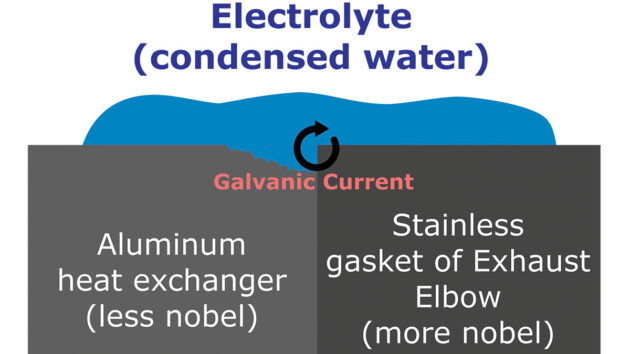
The mode of failure – galvanic corrosion
This, alone, is insufficient, as the studs and nuts will also electrically connect the heat exchanger to the exhaust elbow.
The best idea is to apply Tef-Gel, a product specifically developed to prevent dissimilar metals galvanically corroding, to the studs and
to the nuts that secure on the exhaust elbow.
This will give an extra level of protection.
I did challenge Volvo as to why the elbow and the heat exchanger were not electrically isolated from one another to prevent this from happening; while helpful, the firm responded that this issue is age-related, and that elbows should only last a maximum of 10 years and should be inspected regularly.
Test running and success
By carefully and slowly pouring jugs of coolant directly into the expansion tank, I avoided any air locks.
I ran the engine for some time and all connections appeared fine apart from the mating surface of the thermostat, where it was weeping water very slightly.
After snugging up the bolts a little, taking care not to overdo the torque, as these skinny bolts can easily either strip their threads or sheer off altogether, all leaks were clear, and we once again had a fully functioning, and non-lethal engine.
The whole process, while frustrating at times, gave me a grounding knowledge in this new (to me) frontier of indirectly-cooled engines.
Lessons learned
- A survey can only pick up so much. As skipper, the boat’s safety is your responsibility. I had no carbon monoxide alarm on the return trip from Poole and I had no idea my exhaust system was leaking toxic gas into the cabin from two points (the exhaust elbow and the wet exhaust hose). This could have had fatal consequences.
- I now have at least two carbon monoxide alarms on board and I check them for every overnight stay.
- Don’t assume a replacement is always necessary, regardless of what the manufacturer says. Repairing the existing heat exchanger was not only more cost effective, it was also more ecologically sound.
- Trust your instincts. I should have tried harder to find the source of the smell on that trip and not assumed all was well just because the survey came up clear and an engineer had signed the engine off.
Exhaust elbow repair guide: step-by-step
Credit: Mark Ryan
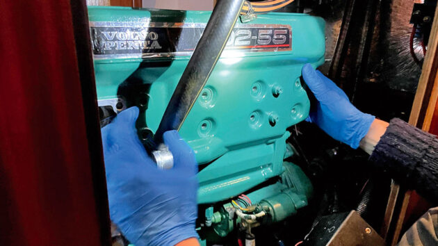
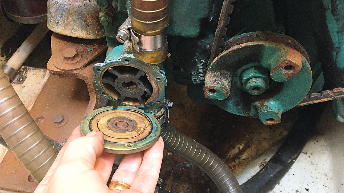
1. Remove the air filter and wet exhaust hose from the engine. The exhaust elbow is located on the port side of the engine. Remove the air filter from the starboard side to make access easier, then move to the port side and remove the wet exhaust hose. This can be tricky, as after many cycles of heating and cooling it can be stuck hard. Waggle the hose about to break the bond.
Credit: Mark Ryan
2. Remove the four nuts holding the exhaust elbow on to the heat exchanger studs. Remove and inspect the exhaust elbow itself, along with the water injection elbow (secured with two bolts onto the exhaust elbow body). If corroded badly, replace with stainless steel parts.
Credit: Mark Ryan
3. Drain the coolant from the engine and heat exchanger, then remove all pipes and fittings from the heat exchanger, including the electrical box on the aft end of the heat exchanger.
Credit: Mark Ryan
4. Once all the pipes and fittings are off the heat exchanger, it is simplicity itself to remove. If you have good access, six bolts and eight nuts will see the heat exchanger easily come away from the engine.
Credit: Mark Ryan
5. Find a specialist aluminium engineering shop, and talk to the engineers about your heat exchanger repairs. Aluminium is tricky to weld and requires specialist equipment and expertise – a bodged repair may mean a heat exchanger replacement.
Credit: Mark Ryan
6. Once you have the heat exchanger repaired, strip the tube stack unit down and remove any scale, salt deposits, or any seaweed and debris. Remove any trace of the old gaskets (quite tricky with the old baked-on paper gaskets). Replace all gaskets and reassemble.
Credit: Mark Ryan
7. Pressure test all three chambers of the heat exchanger and test your thermostat. You do not want to reassemble the engine and then have it leaking sea water, fresh water, or exhaust gases, so pressure test each chamber to 15psi. Getting the ports to seal is an art in itself. At home, test your thermostat opens and closes at the correct temperatures using your stove.
Credit: Mark Ryan
8. Now your heat exchanger unit is functionally perfect, finish off the job by degreasing, lightly rubbing down, and then respraying it with engine enamel, carefully masking off all the ports, electrical bits and labels.
Credit: Mark Ryan
9. Refit the shining, good-as-new heat exchanger with your new stainless steel exhaust elbow and composite gasket, using Tef-Gel on the studs to try and insulate the stainless elbow from the aluminium heat exchanger as much as possible. Test run the engine up to temperature and if all is well, it’s time to celebrate your success!
How to winterise a boat engine
Engineer Stu Davies explains the steps you should take to make sure your boat’s engine is protected over the winter…

5 top causes of boat engine failure – and how to avoid them
Jake Kavanagh talks to Sea Start marine engineer Nick Eales about how to avoid the five major causes of an…
How to service a marine engine cooling system
Is your boat's engine beginning to run hotter than normal? It may be time to service the cooling system, suggests…

How do I tell if an old boat engine is beyond repair?
Is it worth buying a boat with a non-running engine? Vyv Cox has some tips on what to look for…
Want to read more practical articles?

A subscription to Practical Boat Owner magazine costs around 40% less than the cover price.
Print and digital editions are available through Magazines Direct – where you can also find the latest deals.
PBO is packed with information to help you get the most from boat ownership – whether sail or power.
-
-
-
- Take your DIY skills to the next level with trusted advice on boat maintenance and repairs
- Impartial in-depth gear reviews
- Practical cruising tips for making the most of your time afloat
-
-
Follow us on Facebook, Instagram, TikTok and Twitter