
Tony Davies demonstrates how to replace an electro-hydraulic autopilot pump
Not everyone can afford to equip their boat at the chandlers, so for many of us it is a matter of searching boat jumbles and scouring online auction sites for bargains.
Even the YBW forums can be a good source of fairly-priced equipment.
In fact, it was from this source that I bought my autopilot.
The boat in question is a 7.9m (26ft) sport fshing-style vessel, built from scratch on a very tight budget on a hull given to us by Watchet Marina to stop them burning it!
The autopilot, meanwhile, is a Raymarine S3G computer with a compass, rudder reference transducer and a 6002 control unit, all in nearly-new condition.
The spec for this is way beyond what is needed on a 26ft boat, but I’m always happy to over-spec if the price is right and this was around one-third of retail, so well worth having.
The problem with buying second-hand autopilots is that the seller will often upgrade the electronics but keep the drive unit to power the new equipment.
This means that second-hand drive units of whatever type seldom come onto the market in good condition.
Generally, there is no alternative but to buy a new drive, but having saved a fortune on the electronics it is probably worth paying the extra for a new drive which has no wear and tear on it.
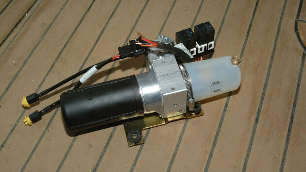
On our boat the steering is hydraulic so we needed a new electro-hydraulic pump.
Pumps are more or less universal, so it is not vital to buy the pump from the same manufacturer as the autopilot.
It is of course essential to ensure that the pump is of the correct capacity to suit the steering ram/s on the vessel, but other than that you can opt for your preferred make of pump.
In our case, we decided to go with Vetus as we have had many years of good service from their equipment and the price for the pump was within our budget.
When specifying the drive unit to suit the steering, and in this case, it is a hydraulic ram, the first step is to find the ram capacity.
This is basically the volume of oil that the ram holds when full.
The capacity is often marked on the ram body, but if the makers’ name and model number are available then the capacity will be available from them.
As a last resort, the capacity can be calculated by measuring the size of ram as this will give a near-enough figure.
The next item is the required pumping capacity of the electro-hydraulic pump to provide the required hard-over to hard-over
times.
For example, our ram has a capacity of about 100cm3 and we reckon a lock-to-lock time of about 10 seconds will provide smooth steering, so we divided 100 (cm3) by 10 (seconds) to give an answer of 10cm3/sec.
This we multiplied by 60 to give a required pump capacity of 600cm3/min.
From this we were able to select our pump, the Vetus EHPB R2 producing 700cm3/min, which is near enough above the required figure.
Having got the brainwork out of the way, the rest was straightforward!
Note: If your steering helm does not have built-in check valves you will need to install one into the system, and these are readily available from Vetus and general hydraulics suppliers. You will know whether check valves are fitted or not by the way your steering operates. If the wheel turns when pressure is applied to the rudder then check valves are not fitted. If the rudder feels solid when pressure is applied to it then check valves are already in place. Many sailing skippers prefer not to have check valves as the steering provides feedback to the wheel in the same way as manual steering, so if an autopilot is being fitted then the ‘feel’ must be forfeited for the pilot to operate.
Getting started on fitting the autopilot pump
The mounting bracket
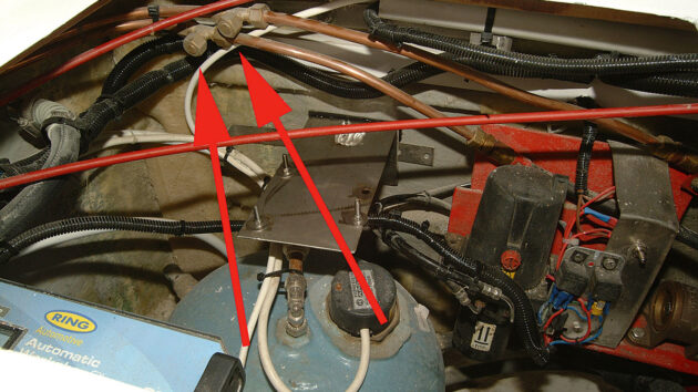
The first job is to install ‘tee’ fittings into the hydraulic steering pipework close to where the electro-hydraulic pump will be installed.
In this case, the ‘tees’ had been fitted and blanked off when the pipework was first installed.
However, the system still required draining to allow the new pipework to be connected.
A simple mounting bracket was made up from scrap stainless steel and bolted through the transom close to the location of the ‘tee’ couplings.
(As you will see later, the position of the bracket was later changed to improve the pipe runs from the pump).
Modifying the pipework from the manual helm pump

1. At the other end of the system it becomes necessary to modify the pipework from the manual helm pump to allow the fitting of an additional pipe from the bottom connection on the helm pump to the top connection on the electro-hydraulic pump. First, the blanking plug is loosened.

2. Next the plug is removed…

3..and the threads cleaned out.

4. A drop of ‘thread lock and seal’ is applied to the new compression fitting and an O-ring fitted.

5. The fitting is then screwed in finger-tight…

6….and tightened with a spanner, taking care not to over-tighten it!
Assembling the pipework

1. Next we assemble the pipework, and for this system, we decided to go for the ease of use of Vetus flexible hydraulic pipework and fittings as these are compatible with copper fittings.

2. The first step is to screw the fitting onto the pipework so that it grips the pipe. They go on quite tightly, so a good grip is required.

3. A drop of hydraulic oil on the threads of the internal fitting makes assembly much easier.

4. The fitting is then inserted into the pipe…

5….and screwed home using a spanner, finally being tightened to provide a perfect seal. As can be seen, the other end of each fitting is the same diameter as a standard copper tube so it connects to compression fittings in the usual manner.

6. The pipework can now be connected.
Credit: www.vetus.com
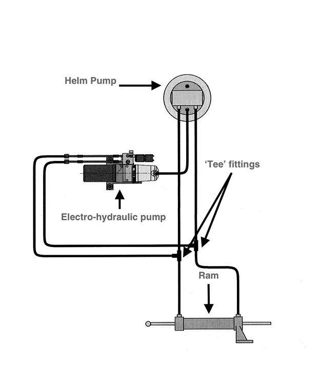
7. The pipework consists of the two pipes from the electro-hydraulic pump to the ‘tee’ fittings and the bleed line from the top of the pump to the bottom connection on the helm pump. If a check valve is required this fits in place of the two ‘tee’ fittings.

8. The pump is now installed in its new position that offers a near-perfect pipe run from the pump to the ‘tees’. Note the pipe coming to the electro-hydraulic pump filler from the helm pump
Bleeding the system
Credit: www.vetus.com
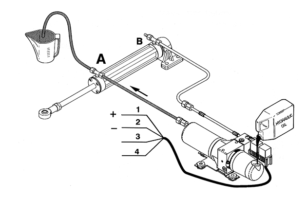
Bleeding the system is exactly the same as bleeding a standard helm pump and ram, except it is necessary to bleed the electro-hydraulic pump as well as the helm pump.
The diagram shows the pump being filled through the reservoir filler, but this is not possible as the bleed line from the helm pump is installed into the filler.
This means it is necessary to keep the electro-hydraulic pump reservoir topped up via the helm pump filler.
Move the ram to position A and open the bleed valve.
Make a temporary connection to the positive cable (red), negative cable (brown) and either the orange or white cable as required, and run the electro-hydraulic pump until air-free oil emerges from the bleed valve and then close the valve.
KEEP THE RESERVOIR TOPPED UP AT ALL TIMES.
Using the electro-hydraulic pump, move the ram hard over to the B position and repeat the above process.
Finally, check the level in the helm pump and re-check the level over the next few days, topping up again as required.
Electrical Connections
The electrics are very simple, consisting of four cables – 1 red (+), 2 brown (-), 3 orange and 4 white – that decide the pump operating direction.
If the pump runs the wrong way once everything is working, all that is required is to reverse the orange and white connections.
Rudder limit settings
Although we used a Vetus electro-hydraulic pump for this installation, there is very little difference in the installation work required should you choose to use another manufacturer’s pump.
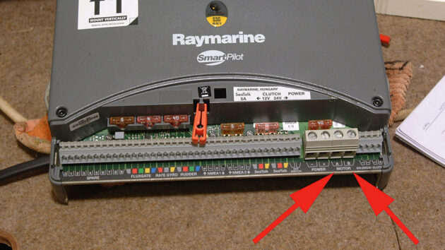
The ‘motor’ connections on the pilot computer (arrowed) are clearly labelled, as are all the other connections in typical Raymarine style.
Also, you may prefer to use copper tube instead of nylon, which again makes no difference to the job other than the additional compression joint assembly.
Most modern autopilots incorporate rudder limit settings to prevent the pilot from driving the rudder hard against the stops.
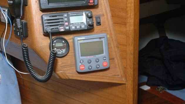
After all the effort of the installation, the only part that is on show is the control unit; in this case a Raymarine ST6002.
These are set during the calibration process before the first sea trial.
If your pilot does not include these settings you may have to install cut-off switches on each side of the rudder arm to cut the power at the end of each stroke.
The pump instruction manual should provide instructions on how to do this.

How to fit your own Raymarine autopilot
Gilbert Park shows how he installed a new Raymarine autopilot on his Trusty T23 motorboat

Milky oil in my saildrive. What do I do?
While changing his engine oil, Chris Mardon noticed milky oil in his saildrive. Will it have caused damage to the…

Replacing a saildrive gaiter: step by step
After seven years of regular use, a saildrive gaiter should be changed before it deteriorates to let water through the…

How to service a marine diesel engine in 12 simple steps
It was time to service the marine diesel engine on our Maxi 84 cruiser. Knowing how to diagnose and fix…
Want to read more practical articles like How to fit an autopilot pump?
A subscription to Practical Boat Owner magazine costs around 40% less than the cover price.
Print and digital editions are available through Magazines Direct – where you can also find the latest deals.
PBO is packed with information to help you get the most from boat ownership – whether sail or power.
-
-
-
- Take your DIY skills to the next level with trusted advice on boat maintenance and repairs
- Impartial in-depth gear reviews
- Practical cruising tips for making the most of your time afloat
-
-
Follow us on Facebook, Instagram, TikTok and Twitter